The "Little Stick" antenna is an aluminium version of the
Vertical Bazooka design which was made from coax.
The "Little Stick" antenna is an aluminium version of the
Vertical Bazooka design which was made from coax.
Both antennas come from the same sleeve
dipole family as the Shakespeare Big Stick that gained enormous popularity amongst CBers and is still widely
in use by Marine Radio operators. Hams have also produced many
variations on the theme like the ones from KV5R and W7LPN .
There is much to recommend this design:
-
Very compact, only a meter tall on 2
meters.
-
No ground radials needed.
-
Fairly broad bandwidth.
-
Low radiation angle.
-
Between 3 and 5db of gain.
-
Low SWR, typically under 1.5 to 1.
But there are also a couple of problems:
There isn't a lot that can be done about the
mounting problem. Because the bottom half of the antenna also radiates
RF, you can't just clamp these antennas to a mast pipe. You need to make
provisions to both insulate it from the support structure and stand it
some distance away from metal objects.
The other two issues are why I wanted to try
building an aluminium version of the sleeve dipole. I wanted to see if I
could overcome some of the construction problems and produce a
professional looking antenna that is adjustable. I believe I've achieved
this by using a rather unique feedpoint construction technique.
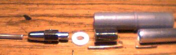
 The parts you will need are shown on the left.
You'll need a piece of 1/2" tempered
aluminium tubing, a piece of 3/16" tempered aluminium rod, two pieces of
.4mm thick brass about 3mm X 40mm, a 3/4" hose joiner, (also called
barbed inserts in the U.S.....search Google),
an AS-1 whip adaptor, an SM-2 antenna bolt and, although not in the
picture, a meter of RG-8X coax a PL-259 connector and an adaptor to fit
the coax to the connector.
The AS-1 and SM-2 antenna parts should be in
stock in most ham shops along with the coax, connector and adaptor. The
aluminium and brass bits can be obtained from most metal supply shops.
The hose joiner is a common hardware item that can be obtained from most
hardware stores or garden centers for a few pennies (buy 3 or 4, just in
case).
There are two kinds of SM-2 connectors. You
want the one with the larger (1/2") brass nut not the ones with the
small (7/16") stainless one.
You should note there are two kinds of hose
joiners, made from different plastics. The black ones won't work in this
application because they appear to be conductive at VHF frequencies.
Make certain you get the grey coloured ones.
Getting Everything Ready
 The first step is to cut the aluminium bits to length.
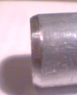
The bottom section is made from the 1/2"
tubing and is 397mm long. The length is determined by the velocity
factor of the RG-8X coax. You can probably cut this most accurately with
a tube cutter. Once you have your cut, take a rat tail file and make
sure there are no sharp edges. Note in the photo on the right that I've
tapered the ends of the tubing on about 45 degrees. This will become
important when assembling the antenna.
You will want to cut the top section too long
so that you'll have to trim it for lowest SWR. I cut the 3/16" rod to
570mm as a starting point knowing I would have to trim it several times
to get the right length. This is a far better idea than starting off too
short and having to cut a longer piece.
Next you want to get the two brass strips
ready to make into your feedpoint contacts. Clean them up with a file,
making sure there are no sharp edges anywhere then tin one side of one
of them with a thin but even layer of solder. The solder helps prevent
interaction between the brass and the aluminium that might lead to
corrosion later on. This layer needs to be very thin because a thick or
uneven layer might make the antenna impossible to assemble.
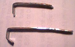 The next step is to form the two brass strips as shown on
the left.
The next step is to form the two brass strips as shown on
the left.
The clip at the top of the picture is made
from the tinned brass and will become the connection between the coax
shield and the lower section of the antenna. The long side is 25mm. The
short side is 6mm long. When you bend it, make sure the solder tinned
side of the brass is on the inside of the bend and you should bend it a
little more than 90 degrees.
The lower clip in the picture will become the
connection for the coax center and the top of antenna. This is the
untinned piece of brass. It will do double duty by providing the
connection and also making sure the top section can't slide down and
short out the antenna. Start with the shortest piece and bend it to 5mm
on a 45 degree angle. The middle piece is also 5mm, bent to 90 degrees.
The remainder of the piece needs to be at least 40mm long and will be
cut to length later.
You should now check again and be sure there
are no sharp edges on the brass clips. It might also be a good idea to
check your bends with a magnifying glass to be sure there are no cracks
in the metal. These clips will be under stress during assembly and you
don't want them to break.
 The next step is to disassemble the SM-2 antenna mount. You
will want to take all the sharp edges off the nut as these may cause
problems during assembly. The image on the right shows how I tapered the
ends of the ridges.
The next step is to disassemble the SM-2 antenna mount. You
will want to take all the sharp edges off the nut as these may cause
problems during assembly. The image on the right shows how I tapered the
ends of the ridges.
And the last step is to take one of the
insulating washers from the SM-2 and file off the shoulder that would
normally keep it centred in a bracket's hole. You will need a flat
plastic washer and this is a very easy way to get one.
Assembling The Antenna
Now that you have the bits and pieces all
ready to go it's time to start assembling the antenna. The pictures
below show how the parts fit together, as a side aligned view, without
the coax in the way...
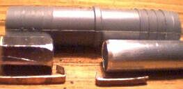
Everything winds up inside the hose joiner.
The antenna uses the pressure from the joiner to make connections by
applied pressure between the clips and the antenna elements. Once the
coax is attached to the clips forcing the hose joiner over the bottom
tube traps the first clip and then forcing the nut into the top of the
hose joiner, traps the other. This will form the feed point. Add the
washer and the AS-1 adaptor and the antenna will have an adjustable top
whip. And as a bonus, it can easily be made fully weather proof.
 The first step in final assembly is to prepare the coax with
the brass clips. Some care is needed here as the spacing of the clips is
quite important. You want the top clip to correctly position itself to
sit a couple of millimeters below the bottom of the nut, when the top of
the bottom tube is at the center of the hose joiner. If it's too long
the clip may be damaged when inserting the nut, if it's too short the
coax center lead may short to the lower element of the antenna. It
should look like the image on the right.
The first step in final assembly is to prepare the coax with
the brass clips. Some care is needed here as the spacing of the clips is
quite important. You want the top clip to correctly position itself to
sit a couple of millimeters below the bottom of the nut, when the top of
the bottom tube is at the center of the hose joiner. If it's too long
the clip may be damaged when inserting the nut, if it's too short the
coax center lead may short to the lower element of the antenna. It
should look like the image on the right.
 Once you are satisfied the clips are positioned correctly,
insert the coax into the lower tube so that the ground clip is on the
outside as shown on the right. Be sure the tapered end of the tube is at
the end where the ground clip is.
Once you are satisfied the clips are positioned correctly,
insert the coax into the lower tube so that the ground clip is on the
outside as shown on the right. Be sure the tapered end of the tube is at
the end where the ground clip is.
Now mark the aluminium tube where the bottom
of the hose joiner will sit if the top of the tube is at the center of
the joiner. This is your target depth when forcing the joiner over the
tube.
The best way to assemble the bottom section
is to get it started as far as you can by hand then gently warm the
plastic with a blow drier. Don't get it too hot; it will melt. With only
a little bit of heat the plastic will relax and let you go a bit more.
Warm it again and then go some more. I put the joiner against a doorjam
and put a wrench on the other end of the aluminium tube to press
against, so I could get more leverage.
A couple of precautions are necessary. Be
very careful not to cut the coax against the bottom of the tube. Also,
the long side of the top clip is going to come out the top of the hose
joiner as you press the lower tube into place, so be sure to allow it to
move freely as you go.
The pictures below show the beginning and
completion of this part of the assembly process.
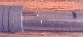

In the right hand picture above you can see
that I've already bent the top clip over. This is to prevent it from
sliding back down into the hose joiner when forcing the nut into place.
At this point you should use an ohm or
continuity meter and make sure the connections to your clips are still
good and nothing is shorted. Measure from the aluminium tube to the
shield of the coax at the far end and from the center clip to the coax
center at the far end to confirm your connections. Finally measure from
the top clip to the tube to make sure it's not shorted. If all is well,
you're all set to insert the nut in the top section.
 The good news is that although still very tight, the nut will go in a
lot easier than the bottom section did. First make sure the upper clip
is laying flat against the inside of the hose joiner --not diagonally
across it. Grip the plastic joiner, press the nut into place, get it
started and push until the top of the nut is flush with the top of the
plastic. When pressing this part into place don't use the bottom tube
for leverage, you might accidentally move it, always grip the plastic
hose joiner. You can use the same technique of warming the plastic a
little as you used on the bottom section if you need to.
The good news is that although still very tight, the nut will go in a
lot easier than the bottom section did. First make sure the upper clip
is laying flat against the inside of the hose joiner --not diagonally
across it. Grip the plastic joiner, press the nut into place, get it
started and push until the top of the nut is flush with the top of the
plastic. When pressing this part into place don't use the bottom tube
for leverage, you might accidentally move it, always grip the plastic
hose joiner. You can use the same technique of warming the plastic a
little as you used on the bottom section if you need to.
 All that remains of the feedpoint assembly is to clip the brass tab off
the side of the nut and assemble the whip adaptor on top.
All that remains of the feedpoint assembly is to clip the brass tab off
the side of the nut and assemble the whip adaptor on top.
To do this, put a little bead of silicon
rubber on the edge of the joiner, place the plastic washer on top and
screw in the AS-1 adaptor. Tighten the adaptor with a wrench, being
careful not to crack the plastic washer and then add another bead of
silicon around the base of the nut, where it mates to the washer.
After the rubber dries, insert the 3/16"
aluminum whip into the AS-1 and snug up the setscrews.
 Annnnd... on the left we see the finished antenna.
The last step is to install the coax
connector on the other end of the coax. I suggest leaving a fair bit of
extra coax on the bottom as you may have to make a choke with it.
I'm a bit fussy about coax length. One trick
to use for single band antennas is to keep the coax a multiple of an
electrical half wavelength long. I doubt this changes antenna
performance much but, because a half wavelength feedline mirrors the
impedance at the far end, it does mean that the readings you take at the
back of the radio are the same as you would get from the antenna's
feedpoint itself.
The general formula to make a half wavelength
of coax is:
Length (in centimeters) == 15000 /
Frequency X Velocity Factor
For RG-8X on two meters this is: 15000 / 146
X .76 == 78.1cm
Installation and Tuneup
I had a bit of trouble deciding how to mount
and test this antenna. A couple of first tries were very discouraging as
the antenna was too near the metal of my balcony. I finally found the
best spot was directly above my balcony rail, on some PVC plumbing pipe,
centered vertically between the railing and the bottom of the balcony
above.
I had no problems getting the SWR down using
the usual method of checking at both ends of the band, trimming and
adjusting the whip, seeking an equal match on 144mhz and 148mhz and
initially ended up with 1.2:1 at both ends with an absolutely flat match
in the center (146mhz). In fact, this antenna adjusts very easily.
Once I found the right spot, the signal
reports were encouraging. It did far better than my 1/4 wave monopole
when talking across lake Ontario. Several repeaters were up an S unit or
more and everyting seemed clearer. Plus there was a noticeable reduction
in noise.
 I also took the antenna out onto the parking lot with my HT and did some
tests there. It seemed quite happy to get away from all the metal on my
balcony and I was able to open a couple of repeaters 50km away with the
HT's medium power setting.
I also took the antenna out onto the parking lot with my HT and did some
tests there. It seemed quite happy to get away from all the metal on my
balcony and I was able to open a couple of repeaters 50km away with the
HT's medium power setting.
For those who want to build and experiment
with this design, keep in mind that you have to keep it at least 30cms
from nearby metalic objects; more space is better.
One of many possible mounting schemes is
shown on the right, using 1/2 inch PVC plumbing parts. The T-fittings
that hold the Little Stick are modified by filing away the internal
ridges to make a slip through fit that goes over the Little Stick's
lower section.
My sense is this is a perfectly good antenna
design that will probably work quite well on top of a mast pipe, out in
free space. It does work from the balcony, better than a 1/4 wave, but
the large amounts of nearby metal do tend to reduce it's performance
somewhat.