THE HENTENNA
RE-VISITED
"The following article has
been re-edited for the English language
from the Japanese
site.
Minor errors and corrections have
been made."
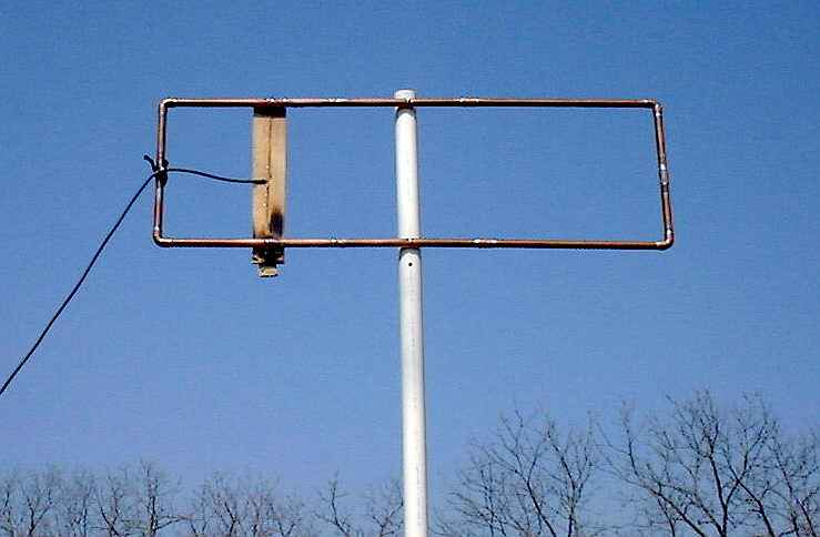
The Hentenna
was developed by Japanese 6 Meter Hams, JE1DEU / JH1FCZ/ JH1YST in the
1970's and can be designed and built for hf thru uhf and possibly
beyond!
After much
experimentation, finally, the antenna was developed with good
performance, however, it was difficult to explain why the performance was
so good, or how it is worked basically at that time. So it was named
Hentenna ,
"Hen" means "strange" in Japanese.
The
antenna has good performance and many advantages and it has become very
popular in Japan. Many JA stations make it and enjoy it at home or
in the field. Some Japanese 6m beacon stations are using the Hentenna
antenna.
HERE ARE SOME GOOD POINTS FOR THE HENTENNA
1. Good
performance
2.5-3 dBd gain
Low angle radiation
*
Total performance is equivalent to 2-3 element Yagi-uda
antenna,
Wide band width
2. Easy to make
It is possible to adjust impedance and SWR
perfectly, This means, not so difficult to make!
No special parts are
required. You can useany
electrical conductor to make the main rectangle.
Broad
adjustment ....wide bandwidth
3. Easy to build
up
If you use thin aluminum pipe and thin wire, you can
make this antenna for 6m very light. It can be designed for most any
band or frequency by using the included formulas below.
Due to
it's construction, it is easy to put it in a higher position in the air.
You can also use light mast for it.
As this is a vertically long
antenna, it is easy to install the antenna on a veranda or small
space.
It appears to be a vertical antenna but has
mainly
Horizontal radiation:
This is
one of the reasons this antenna is "Hen",
(STRANGE)

This antenna is shown in drawings above horizontally
polarized....
lay it on it's side for vertical polarization.
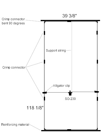
Also
please note in the above English drawings that the Hentenna is basically a
loop fed about 1/10 wavelength from the bottom element with 50 or 75 ohm
coax attached to the top element of the bottom loop at the center
point.
Hentenna
Basics
1. Basically 1 1/3 WL Loop antenna around outer edge of antenna
2.
L1 works as 1 loop antenna
3. L2 works as matching
section
4. Vertical long rectangle has more gain than ordinary
square loop and has less impedance.
L2 helps the matching and low angle
radiation.
5. 3D pattern is like shell of peanut (maximum gain
directions looking at you and away from you) so it will be somewhat
bi-directional.
How to
Adjust
1. Move the "a" and "b" points to adjust swr. (move in
equal amounts), move towards top (in the drawing) to increase
resonant frequency,
move towards bottom to decrease resonant
frequency.
2. SWR may be higher than 1:1.5 at first so move
matching points "a" and "b" in small increments up or down the loop until
lowest swr is obtained and secure at these points with whatever method you
choose depending on your construction materials. The overall outside
(total) length may have to adjusted a small
amount also.
The construction materials you use for the
loop will determine how the antenna is supported.
It will weigh more if
made from aluminum or copper tube.
It will require a non
conductive support mast or structure to attach it even if made from wire.
Nylon cord or rope, heavy string or other non conductive material can
be used for support at the four corners.
A length of pvc
pipe, plexiglass, wooden dowels, etc can be used as support
for the top, bottom and coax feed point elements with the side wires
strung between them or can be used to completly enclose the wire.
Use
your own design.
Most JA hams use wire
construction.
The final configeration in the air should be as close to a
vertical rectangle as possible.
This antenna
is shown in drawings above horizontally polarized....lay it on it's side
for vertical polarization.
Experiment with
your favorite support and try to keep conductor size under 1/4 inch. See
the Japan site link below for more
info.
+++++++++++++++++++++++++++++++++
6 Meter
Version
THE
MATH
Calculating the lengths for the Hentenna is simple and
straightforward and can be used for HF THRU UHF and possibly
beyond.
The formulas below will get you in the ball park for most any band or
frequency. There are two methods for getting the approximate lengths.
Chose the one that works best for your math
abilities.
First method
formulas:
Just start with 1
meter = 39.36 inches
1 inch = 2.54
cm
1 wavelength = 6 meters = 6 x 39.36 = 236.16
inches
(Remember, this is not a 1 wavelength loop! It is 1 1/3
wavelength)
1/2 wavelength per side = 3 x 39.36 =118.08 inches
1/6
wavelength = 6/6 =1 wavelength = 39.36 inches
1/10 wavelength = 236.16
x .1 = 23.61 inches
Second method formulas (The easiest)
These formulas were extrapolated from the Japaneese
plans and should yield lengths that are a bit long for easier final
tuning.
15744 / Freqmhz
= total outside length in inches of the "rectangle"
5904 / Freqmhz =
1/2 wavelength in inches
1968 / /Freqmhz = 1/6 wavelength in
inches
1180 / Freqmhz = 1/10 wavelength matching section
feedpoints
Using these formulas in
an example for 146mhz center frequency:
15744 / 146 = 107.83 inches total
conductor length (1 1/3 wavelength)
5904 / 146 = 40.43 inches (1/2
wavelength sides each)
1968 / 146 = 13.47 inches (1/6 wavelength
in inches) (top and bottom length as in drawing above)
1180 /
146 = 8.08 inches (1/10 wavelength for matching section feedpoint distance
from bottom of antenna.) (Coax feed point distance from
bottom)
Some adjustment of lengths may be required for peaking at
design frequency. Experiment!
From the above method calculations we arrive at the lengths for
the 6 Meter Hentenna:
1/2 wavelength sides = 118.08 inches
each
1/6 wavelength top, bottom and coax connection element = 39.36
inches
1/10 wavelength matching point = 23.61 inches up from each side
of bottom element.
The 2 Meter example yields these
lengths:
40.43 inches (1/2 wavelength sides
each)
13.47 inches (1/6 wavelength in inches) (top and bottom
length as in drawing above)
8.08 inches (1/10 wavelength for
matching section feedpoint distance from bottom of antenna.) (Coax feed
point distance from bottom)
Total distance around the rectangle =
107.83 inches.
Again,
take notice that this is not just a full wave
loop!
At 6 meters, the total length
around the outside of it is 314.88 inches which comes out to
be