Step One: Better Audio Response from the Yaesu MH-59A8J

897

If you own a Yaesu rig and use the MH-59A8J microphone, you may have noticed that this microphone has a pronounced roll-off of low frequencies.  While this might be desirable in certain mobile or portable applications, it really is tough to live with if you prefer your audio to be more natural sounding with better low end frequency response.  Surprisingly, it appears that Yaesu went out of its way to mechanically block the port in the front of the mic case to produce the restricted audio effect.  Taking the mic apart reveals that only 2 of the holes in the front of the case are actually open, and they are quite small, forming an audio high pass port. They also placed a plastic baffle between the mic case and the electret element, further restricting any chance of lower frequencies from getting through. They also saw fit to place the mic element in a small rubber boot that blocks about 50% of the holes in the front of the electret mic cartridge, which again reduces the low frequency response of the element.  I chose to work on all three of the mechanical restrictions to see what the result might be, and am very satisfied with the audio reports I have received since opening the mic up.  Directions for modifying the mic are below:


  1. Remove the back of the microphone case. (3 screws)
  2. Lift off the PTT lever.
  3. Lift off the UP/DOWN key assembly at the top of the mic.
  4. Remove the 3 visible screws, one in the upper left, two near the crystal.
  5. Remove the small screw fastening the PTT micro switch through the board to the mic front casing.
  6. Gently lift the board away, all that is holding it now is the glue around the mic element.
  7. Peel away the glue holding the mic element in place, and lift it away from the mic front casing.
  8. Remove the plastic baffle insert in the molded mic housing.
  9. Remove the black windscreen material from the molded mic housing and set it aside for later.
10. Slightly enlarge the two holes in the mic front casing with a small screwdriver or drill bit. (See Note 1 below)
11. Carefully remove the black rubber boot from the electret element, it slides right off.
12. Enlarge the hole through the front of the boot to open access to all the holes in the mic element.
13. Place the black rubber boot back onto the electret element.
14. Put the black windscreen material back into the molded mic housing.
15. Carefully guide the mic element back into the molded mic housing.
16. Reassemble the microphone.

Note 1: A slot would enhance the low end response even more, but it could get ugly if you are as inept as I am with tools...

Note 2:  I found that padding the little cylinder found on the inside front of the mic that the electret element sits in with about 1/8 inch of loosely packed cotton was effective in reducing the wind pop issue considerably when talking directly into the mic. It is worth experimenting with, but keep in mind that if you pack it in too tightly you will reduce the mic sensitivity significantly.
Another way to approach this is to put a small circular bandaid over the tiny holes that form the mic port in the front of the mic. I simply took one of these and used a black Sharpie marker to color it to match the mic and 99% of the wind pop issue went away without any degradation of the microphone's performance.


Step Two: Better Audio Response from the Yaesu MH-59A8J

1.  Remove the back of the microphone case.  (3 screws)
2.  Lift off the PTT lever
3.  Lift off the UP/DOWN key assembly at the top of the mic.
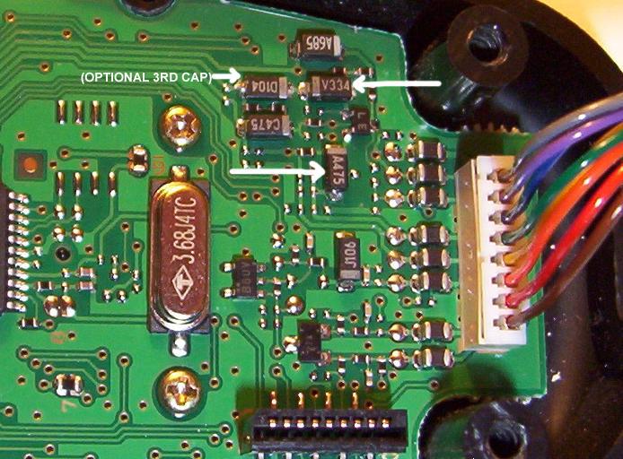
4.  Locate the caps that are to be bridged. (Note in Picture A below the caps with white arrows pointing to them.)


caps

Picture A:  Components To Bridge Across

5.  Solder a 1.0uf tantalum or electrolytic cap across the two caps (V334 and A475) on the board, being careful to work quickly so you do not destroy the tiny solder pads.  Note the position of the positive leads in reference to the board in the picture below.  Bend the caps down to get them out of the way, and put some double-sided tape underneath them to keep them from moving or otherwise stressing the solder joints.


padded

Picture B: Two cap modification

You can certainly experiment with the values of the caps you select to pad with.  Values between 1.0uf to 10.0uf should work fine, with higher values favoring more low end response.  I found the additional two caps to produce pleasant sounding audio, but eventually added a third cap (a 10.0uf tantalum) across component D104 which is just to the left of component V334 (label is  upside down in the photo above). The D104 surface mount cap is in series with the audio from the electret and padding that brings up the low end significantly.  Note that a 1.0uf cap will work just as well here. I liked the result, so my arrangement now has the third tantalum soldered in place as shown in Picture C. 

3 cap mod

Picture C: Three cap modification

The resulting audio is very full and smooth sounding and reports have been extremely favorable.  The thin sounding audio of the stock components is just a bad memory.  Keep in mind that the total audio gain is increased with these arrangements, so you will most likely need to lower your mic settings in the FT-897 menu.  As an example, I went from a setting of FM MIC GAIN =55 to a setting of FM MIC GAIN=20.


Parts List:   

(2) Radio Shack Part  # 272-1434  1.0uf Tantalum Capacitor 35WVDC max
(1) Radio Shack Part   #272-1436 10.0uf Tantalum Capacitor 16WVDC max


Disclaimer:  As always, should you or any of your IM Force be caught or killed, the secretary will disavow any knowledge of your actions. This recording will self-destruct in five seconds. Good luck, Jim.  Also, if you mess your MH59A8J up, I am not responsible.

 Return to Main Page