An end-fed aerial is any piece of wire, metal tube or pole, where the RF signal is fed into it at one end rather than the middle or somewhere else along its length. The wire or pole may be vertical, sloping, horizontal, V-shaped, inverted V, inverted L,or whatever. If you stuff the RF into one end of the thing, then it’s an end-fed aerial. Most CB vertical aerials adorning chimneys and scaffold poles are end-fed. All mobile aerials, mag-mount and the like, are end-fed.
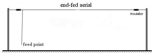
The RF circuit of an end fed wire antenna:
An end-fed horizontal antenna and the ground can be thought of as a simple RF circuit consisting of a wire, a source of RF energy (the transmitter), and the ground. When an RF signal is applied to the antenna, it creates an electric field around the wire, which in turn induces a current flow in the wire.
The basic RF circuit of an end-fed horizontal antenna and the ground can be represented using a simplified equivalent circuit consisting of a series capacitance and an inductance. The capacitance represents the capacitance between the antenna wire and the ground, while the inductance represents the inductive reactance of the wire.
DOES LENGTH MATTER?
The answer to this question is, yes and no. I use 150 feet of wire on all bands between 160 and 10 metres and it works pretty well. Let’s not get bogged down with aerial resonance at this stage. Full-wave, seven-eights, five eights, half-wave, quarter-wave… At the moment, we’re talking about an end-fed piece of wire of random length. We’ve slung the wire out of the shack window and secured the end to some distant tree or whatever. By connecting the shack-end of our wire to a simple L-network matching until, we will be able to work on any frequency between 160 and 10 metres. That’s right, our random length of wire is an all-band aerial. It won’t be the best of aerials, but it’s an all-band aerial.
While talking about this aerial, we’re assuming that we have some sort of earth system connected to our transmitter. OK, so you’re wondering what happened to formulae, cutting the aerial to length for the band we wish to use. Forget all that for the time being. If the aerial happens to be too short for a particular band, we can adjust the inductor in the matching unit to ‘electrically’ lengthen the aerial. If the aerial is too long for the band in use, by changing the configuration of the matching until, we can adjust the capacitor to ‘electrically’ shorten the aerial. More on that later.
Any old length of virtually any old piece of wire coupled via a coil and capacitor network to your transmitter will work on any old band. If that frightening term SWR is looming in your mind, then don’t worry. Our matching network will give you 1:1 SWR. OK, you’re now thinking: twelve feet of wire isn’t going to do a damned thing. You’ve heard that a half-wave aerial for top band should be around 240 feet long. You’re right, but twelve feet of wire will work on top band. Not very well, but it will work.The whip aerials on armoured vehicles, tanks, jeeps and the like, are twelve feet long. And the army use a host of frequencies between top band and ten metres. If you want to argue about that, then go and annoy the army.
So what’s all this stuff about aerial resonance, length, feed impedance… Let’s assume that our random length of wire happens to be 16 feet. Not much of an aerial, you might think. And not much of a back garden if that’s all you can fit between the house and the XYL’s washing line pole. But, 16 feet happens to be a quarter-wave on 20 metres. How do I know that? Because the formula to work out a half-wavelength is 468 divided by the frequency. So, as 14.2mHz is somewhere in the middle of the 20 metre band, then 468 divided by 14.2mHz gives us 32.9 feet. As 32.9 feet is the length for a half-wave, we divide this by 2 which gives us around 16 feet. This means that our wire is a quarter-wave on 20 metres.
Let’s do that again. Say we want to make a quarter-wave aerial for the 40 metre band. OK, 468 divided by 7.05mHz (the middle of the band) equals 66. That’s 66 feet, which is a half-wave on forty metres. You want a quarter wave on 40 metres? OK, 66 divided by 2 gives us 33 feet. If you feel bogged down at this stage, then take up fishing.
Seriously, there’s nothing to it. You want a quarter-wave whip aerial on top of your car to work on 29mHz. OK, 468 divided by 29 equals 16. Right, 16 divided by two equals 8. That’s eight feet. Trim the length of your whip to get the SWR down to 1:1 and you’re mobile on 10 metres.
Why are we talking about quarter-wave aerials? Because I’ve been cheating. Not cheating, exactly. But certainly making things easier at this stage. It so happens that the feed impedance of a quarter-wave aerial is around 50 ohms. That figure rings a bell. Oh, yes. 50 ohms happens to be the output impedance of our transmitter. How bloody convenient. Why is it convenient? Because we can forget about an aerial matching until. Mobile CB aerials are connected directly to the socket on the back of the rig. There’s not a matching until in sight because the radio is 50 ohms and so is the aerial. The same goes for 2 metre mobile aerials. Right, are you happy with that? Good.
Now to chuck a spanner into the works. Our wire aerial is 16 feet long. Great for 20 metres where the feed impedance is 50 ohms and we don’t need a matching unit. But we’re going to use this aerial on 10 metres. The aerial on this band is a half-wave. Is that so bad? Half-wave aerials are great, aren’t they? Yes, but the feed impedance of our aerial on 10 metres is something horrendous. We’re looking at a feed impedance of around 5000 ohms! Don’t worry, the aerial matching unit will deal with it.
QUARTER-WAVE VERTICAL
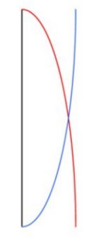 You may have heard people talking about their aerials being either current fed or voltage fed. Take a look at the diagram on the left. The black vertical line represents a vertical aerial. Let’s assume that it’s about 16 feet long and mounted on the ground. This is a quarter-wave end-fed vertical for 20 metres. The red line represents the current in the aerial. This is a section of a sine wave, showing maximum current at the bottom of the aerial and zero current at the top. If we feed this aerial at the bottom, then it is current fed. Why? Because we’re feeding the thing at the point where maximum current occurs.
The blue line represents the voltage in the aerial. Zero voltage at the base and maximum at the top. Without altering the aerial or changing the frequency we are using, we can’t change the voltage or current patterns. If fed at the bottom, then this particular length of aerial when used on 20 metres is current fed, and that’s that.
HALF-WAVE VERTICAL
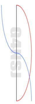 If the aerial were twice as long and we still used it on 20 metres, then it would be a half-wave end-fed vertical. The diagram on the left shows what happens to the current and voltage in our half-wave vertical on 20 metres. At the bottom of the aerial the current is now zero, shown by the red line. The blue line shows the voltage as being maximum and the bottom. This aerial is voltage fed. You’ll notice that the current is not only zero at the bottom, the feed point, but also at the top. Maximum current occurs in the centre of the aerial, and it is at this high current point where maximum radiation of our signal occurs.
So what does all this mean? Voltage fed, current fed… So what? The feed impedance of our quarter-wave vertical is very low. In fact, at the base where there is maximum current, the feed impedance is around 50 ohms. Pretty handy, don’t you think? Of course it’s handy. Our transmitter wants to ‘see’ 50 ohms, our coax is 50 ohms, our aerial is 50 ohms… Great, no matching unit required.
On the other hand, if we feed our half-wave vertical aerial at the base where the voltage is high, the feed impedance may well be around 5000 ohms. To feed this aerial with 50 ohm coax, we’d have to place an aerial matching unit at the base of the aerial. There is a way round this problem. Feed the half-wave aerial in the centre where the current is at maximum and the feed impedance is around 50 to 70 ohms. OK, so we turn the pole to a horizontal position, cut the middle, and feed it with coax What have we got? Yes, a half-wave dipole. Of course, we’d use wire rather than a pole to construct the horizontal dipole. There will be a page dedicated to half-wave dipoles so I’ll not go into detail here.
In the diagram below, the black horizontal line represents a 2 wavelength end-fed aerial for 20 metres. This is a pretty long aerial for the band. You can see the relationship between the voltage (V) and current (I) along the length of the aerial. Going back to our quarter-wave vertical aerial, you can see on the diagram below that the voltage at the feed point is zero and the current maximum. Where the aerial ends (at the 1/4 point) the voltage is at maximum and the current zero.
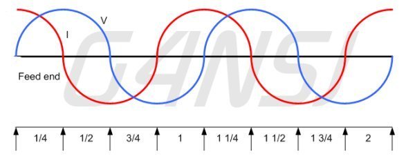
OK, this is where things appear to go wrong. You would think that, by looking at the diagram, our second aerial, the half-wave vertical, is current fed. After all, the current at the feed point is at maximum. However, when an aerial is one half-wave length long, the current and voltage shift along the wire. Our half-wave aerial on the black line above begins at the first zero current point and ends at the next zero current point. In the centre of our half-wave, we have maximum current and zero voltage.
Don’t let all this confuse you. What we’re interested in is getting aerials up and using them. However, it’s good to know a little about what’s going on in the wire, pole, or whatever.
RADIATION RESISTANCE
Basically, this is the resistance that, if inserted in place of the aerial, would consume the same amount of power that is radiated by the aerial. Let’s not get ourselves bogged down with formulae and heavy mathematics. Thankfully, such terrifying things are outside the scope of this article. As far as we are concerned, the radiation resistance of an aerial is the feed point impedance. The radiation resistance of a centre-fed half-wave dipole is between 50 and 70 ohms.
I’m often asked which type of wire to use for an end-fed or dipole antenna. I know that some 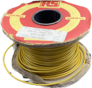 people use flex weave or whatever it’s called. But I use ordinary hook up wire, as shown here. It’s fine for a few years, and it’s relatively cheap. There are colours other than yellow! Blue is good for Australia as the sky is blue. Grey is good for Britain as the sky is grey.