Specifications for Feed Line at bottom of diagrams

The diagram below is of my new and improved 9 to 1 linear matching transformer that is used on the radio end of the feedline.
You can substitute this instead of the Two 300 ohm Matching Stubs /
(Transformers) and the 1 to 1 current balun that you see on the diagram above.
Balanced Self Matching Feed Line System
I Designed this Balanced Self Matching Feed Line System for people who want the very best feed line they can have on a Monobanded antenna. My new and improved 9 to 1 linear matching transformer on the radio end of the feedline. Has such an incredibly low insertion loss you probably could not measure it accurately. I estimated it to be in the hundreds (0.01 db) of a decibel. Here is a list of advantageous for using Balanced Feed Line
Number 1
The line loss per 100-ft. is so low on 450-Ohm Ladder Line you can run 500-ft. and have less power loss than with 100-ft. of RG-8U on all Frequencies up to 148.00-MHZ. A another way to say it is 100 feet of ladder line at 148.00-MHZ has the same loss as 100 feet of RG-8U at 3.50-MHZ. Even 7/8" Hard-Line Coax has a loss of 0.70-DB at 148.00-MHZ per 100ft. conpaired to 0.35-DB for Ladder Line.
Number 2
Feed Line Radiation is eliminated this improves the asymmetrical pattern of the antenna.
Number 3
Ground Wave and Surface Wave propagation of man made noise that induceds it's self on to the braided shield of coaxial cables is eliminated.There by improving signal to noise ratio on your receiver.
Precisely tuning the feedline
When a feedline has an excessive amount of reactance there is always two ways to adjust the feedline. You can either increase its length or decrease it.
For example What ever reading you have on the end of the feedline be it capacitance reactance, inductance reactance or a perfect match.
If you add 1/2 wavelength to the feedline the reading will not change it will be identical to what it was before you added the half wavelength more.
On the other hand if you add a quarter of a wavelength it will add inductance reactance or if you shorten the feedline 1/4 wavelength it will add capacitance reactance.
If you add three-quarters of a wavelength to the line it will add inductance reactance.
On the other hand if you subtract three-quarters of a wavelength it will add capacitance reactance.
In a lot of cases the length of the feedline may only need to be increased or decreased by no more than a 1/ 8 of a wavelength.
You will need to do whichever one of these methods is most convenient for you to obtain a perfect match on the feedline.
This is the best way to precisely tune the feedline.
One Wavelength Loops & Quads
To Match the 100-Ohm input impedance of a One Wavelength Loop or a Quad. You take a 1/4 Wavelength of 450-Ohm Ladder Line and connect it in parallel with the antenna input and the feed line .
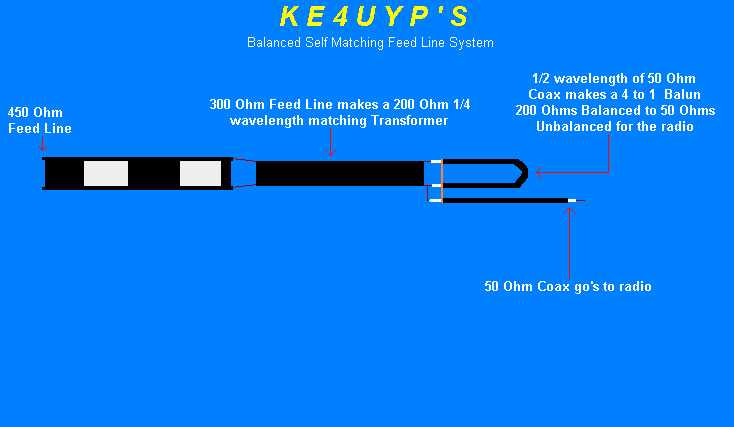
If you look at my diagram you will see how to put the feedline together. The spacing between the 450 ohm ladder line transformer and the feedline is actually 0.0 inches. I separated it in the diagram just for clarity. The two pieces of 300 ohm line are also sandwiched to gather I use nylon tie wraps this holds them tightly together.
This makes a 225-Ohm Matching Stub (Transformer). This Transforms the 100-Ohm input impedance of the Loop antenna up to the 450-Ohm feed line. On the radio end of the feedline you make one quarter wavelength long matching Stub (transformer) out of 300-Ohm low loss Foam Dielectric twin-lead.
This makes a 200-Ohm Matching Stub (Transformer) this Transforms the 450-Ohm feed line down to a 200-Ohms Balanced output. You connect one end to the 450 Ohm feed line and the other end connects to the 4 to 1 Coaxial Balun the output of the Balun goes to the radio 50 ohms Unbalance.
Or you can use my old design. On the radio end of the feed line you make two 1/4 Wavelength long Matching Stubs out of 300-Ohm low loss Foam Dielectric twin-lead and put them in parallel.
This makes a 150-Ohm Matching Stub (Transformer) and this Transforms the 450-Ohm feed line down to a 50-Ohms Balanced output. You connect one end to the feed line and the other end to a 1 to 1 current balun the output of the balun goes to the radio. To Match One Wavelength Loops on 40m 80m and 160m use a 1/4 Wavelength or a 3/4 Wavelength of 75-Ohm-Transmitting twin-lead from antenna input back to the 1 to 1 current balun at the radio. S.W.R. will be 1-to-1.
Inverted-V
To Match the 50-Ohm input impedance of an Inverted-V you make two 1/4 Wavelength Matching Stubs out of 300-Ohm low loss Foam Dielectric twin-lead and put them in parallel This makes a 150-Ohm Matching Stub (Transformer).
The spacing between the two pieces of 300 ohm line is actually 0.0 inches. I separated it in the diagram just for clarity.
I use nylon tie wraps this holds them tightly together.
Connect one end to the feed line and the other end to the antenna input. This Transforms the 50-Ohm input impedance of the Inverted-V antenna up to the 450-Ohm feed line. On the radio end of the feedline you make one quarter wavelength long matching Stub (transformer) out of 300-Ohm low loss Foam Dielectric twin-lead.
This makes a 200-Ohm Matching Stub (Transformer) this Transforms the 450-Ohm feed line down to a 200-Ohms Balanced output. You connect one end to the 450 Ohm feed line and the other end connects to the 4 to 1 Coaxial Balun the output of the Balun goes to the radio 50 ohms Unbalance.
Or you can use my old design. On the radio end of the feed line you make two 1/4 Wavelength long Matching Stubs out of 300-Ohm low loss Foam Dielectric twin-lead and put them in parallel.
This makes a 150-Ohm Matching Stub (Transformer) and this Transforms the 450-Ohm feed line down to a 50-Ohms Balanced output. You connect one end to the feed line and the other end to a 1 to 1 current balun the output of the balun goes to the radio. To Match Inverted-V's on 40m 80m and 160m use a 1/4 Wavelength or a 3/4 Wavelength of 75-Ohm-Transmitting twin-lead from antenna input back to the 1 to 1 current balun at the radio. S.W.R. will be 1.5-To-1. With a 1.5 to 1 S.W.R., your power loss will be 4 Watts out of 100 Watts. Most antenna tuners have at least 27 Watts of insertion loss, with a 3 to 1 S.W.R. line mismatch.
Horizontal Dipoles
To Match the 73-Ohm input impedance of a Horizontal Dipole. You take a 1/4 Wavelength of 300-Ohm low loss Foam Dielectric twin-lead and connect it in parallel with the antenna input and the feed line.
The spacing between 300 ohm line and the feed line is actually 0.0 inches. I separated it in the diagram just for clarity.
I use nylon tie wraps this holds them tightly together.
This makes a 180-Ohm Matching Stub (Transformer). This Transforms the 73-Ohm input impedance of the Horizontal Dipole antenna up to the 450-Ohm feed line. On the radio end of the feedline you make one quarter wavelength long matching Stub (transformer) out of 300-Ohm low loss Foam Dielectric twin-lead.
This makes a 200-Ohm Matching Stub (Transformer) This Transforms the 450-Ohm feed line down to a 200-Ohms Balanced output. You connect one end to the 450 Ohm feed line and the other end connects to the 4 to 1 Coaxial Balun the output of the Balun goes to the radio 50 ohms Unbalance.
Or you can use my old design. On the radio end of the feed line you make two 1/4 Wavelength long Matching Stubs out of 300-Ohm low loss Foam Dielectric twin-lead and put them in parallel.
This makes a 150-Ohm Matching Stub (Transformer) This Transforms the 450-Ohm feed line down to a 50-Ohms Balanced output. You connect one end to the feed line and the other end to a 1 to 1 current balun the output of the balun goes to the radio.To Match Horizontal Dipoles on 40m 80m and 160m use a 1/4 Wavelength or a 3/4 Wavelength of 75-Ohm-Transmitting twin-lead from antenna input back to the 1 to 1 current balun at the radio. S.W.R. will be 1.5-To-1. With a 1.5 to 1 S.W.R. your power loss will be 4 Watts out of 100 Watts. Most antenna tuners have at least 27 Watts of insertion loss, with a 3 to 1 S.W.R. line mismatch.
450-ohm Line=1/4-wavelength
2m=1ft. 7" 1/4
6m=4ft. 6"
10m=8ft. 2"1/4
12m=9ft. 4"1/4
15m=11ft.
17m=12ft. 10"3/4
20m=16ft. 6"
300-ohm Line=1/4-wavelength
2m=1ft. 4"3/8
6m=3ft. 9"1/2
10m=6ft. 10"3/4
12m=7ft. 10"5/8
15m=9ft. 3"1/4
17m=10ft. 10"1/4
20m=13ft. 10"1/2
1/4 Wavelength of Coax
With A Velocity Factor of 78%
Note length shown for center of Band
10 Meters 6 Ft. 8 3/4"--------- (205.105) CM
12 Meters 7 Ft. 8 1/4"--------- (234.315) CM
15 Meters 9 Ft. 0"-------------- (274.320) CM
17 Meters 10 Ft. 7"------------ (322.580) CM
20 Meters 13Ft. 6"------------- (411.480) CM
30 Meters 19 Ft. 2"------------ (584.200) CM
40 Meters 26 Ft. 8 3/4"------- (814.050) CM
80 Meters 51 Ft. 1 3/4"------ (1558.925) CM
160 Meters 102 Ft. 2 1/2"--- (3115.310) CM
1/4 Wavelength of Coax
With A Velocity Factor of 66%
Note length shown for center of Band
10 Meters 5 Ft. 8"-------(172.720) CM
12 Meters 6 Ft. 6"-------(198.120) CM
15 Meters 7 Ft 7"--------(231.140) CM
17 Meters 8 Ft. 11"------(271.780) CM
20 Meters 11 Ft. 5"------(347.980) CM
30 Meters 17 Ft. 0"------(518.160) CM
40 Meters 22 Ft. 8"------(690.880) CM
80 Meters 45 Ft. 4"------(1381.760) CM
160 Meters 90 Ft. 8"-----(2763.520) CM
Back to home page