In Oscar News 211, we looked at how a modern commercial Satellite TV LNB can be used to receive signals from the narrow band transponder on Es’hail-2. An LNB converts the X-band signal from 10.489 GHz, down to an intermediate UHF frequency of 739 MHz. This can be received directly using a FUNcube dongle with a PC, laptop or tablet running suitable SDR software.
While the PLL technology used in the current generation of LNBs produces low phase noise, it was demonstrated that the frequency drift with temperature, could be improved by replacing the 27 MHz reference crystal with a temperature compensated crystal oscillator (TCXO).
Personally, I like seeing the transponder passband on a big screen and being able to click on new stations appearing as they start to call CQ. – So much easier than slowly sweeping a VFO over 250 kHz trying to find a weak DX station.
There will however, also be occasions when using a computer is impractical. – Bright sunlight, poor audio from speakers or simply having too much equipment to make portable operation simple and easy. Under these conditions using a LNB with a conventional radio has several advantages including being able to use a transceiver for generating the uplink on S-band.
Presented in fig.1 is the circuit of a UHF to VHF converter for use with Es’hail-2 / QO-100. It includes a bias tee to feed DC power to the LNB and a mixer that converts the 739 MHz from the LNB down to the 2m band.

Figure 1 Converter circuit diagram
Circuit description
A supply of 12V is applied to the DC input where series diode, D1, protects the converter from reverse polarity. The supply passes through inductor L1 to connector J1 where it travels along the coax to power the LNB. The RF output at 739 MHz from the LNB passes along the same coax in the opposite direction arriving at connector J1. L1 acts as an RF choke and the signal is AC coupled through C1 to 50 ohm power splitter, R1 R2 and R3. The power divider attenuates each output by 6dB. The signal at the lower end of R2 is applied to resistive attenuator R7 R8 and R9. This adds another 12dB of attenuation to the signal which is AC coupled to J2. Although 18dB of loss seems a lot, a typical LNB will have 40 – 60dB of conversion gain and so some attenuation is needed to avoid receiver overload.
The UHF output from J2 can be used to drive a FUNcube dongle or other software defined radio. The second output from the power divider appears at the left hand end of R3. This signal will be mixed down to 2m, but first it passes through an image rejection filter L2 L3 and C3. This high pass filter has a cut off frequency of 700 MHz and has 14dB of loss at the image frequency of 450 MHz. While 14dB is not much, the LNB has its own internal filtering to reduce signals below 750 MHz. In combination there sufficient image rejection to prevent noise degrading the wanted signal at 2m.

Figure 2 Homemade PCB ready to be etched
The HPF is followed by another 50 ohm attenuator. R4 R5 and R6 reduce the level of the signal so that it does not overload the mixer or the 2m receiver. It also provides a nice match into the RF port of the ADE-5 which is a Mini-Circuits double balanced diode ring mixer.
The local oscillator, IC2, is a custom made part (2) available from Digikey and deserves an explanation as it is the modern alternative to the crystal and multiplier chain. The Silicon Labs Si590 is a 6 pin 7 x 5mm module which has an internal oscillator in the 4 GHz range. It also contains DSP electronics to divide the signal down to our local oscillator frequency of 595.000 MHz. AMSAT-UK is using the CMOS and LVPECL versions in the ESEO satellite payload, so this family of devices has seen a lot of use and testing over the past few years.

Figure 3 Output of the Si590 local oscillator module
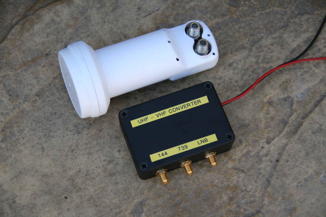
Figure 4 Completed downconverter with Octagon LNB
As part of the programming service, Digikey take a blank generic Si590 which has the required frequency and thermal specification, in this case 20 ppm frequency and 7 ppm thermal stability. Then they program the part to your specification. This defines the output stage to either LVPECL or LVDS logic, both of which have differential outputs. You also need to define the frequency and the supply voltage from 3.3, 2.5 or 1.8V and if you want the output enable pin to be active high or low. In this circuit, enable is active high and an internal pull up resistor allows the pad to be left open circuit. In a test of thermal stability, I cooled the device from +30 degrees to -10 degrees. The part was seen to be 6.7 kHz low at 30 degrees and on cooling by 40 degrees moved to 1 kHz above the specified frequency.
My original intention was to use the differential outputs from a Si590 with a mixer that had an isolated winding for the local oscillator. Unfortunately, despite a lot of searching through data sheets and exchanges with Mini-circuits Tech-Support team, we were unable to identify a suitable differential input mixer.
Anyway, this Si590 requires 3.3V at 80mA from regulator IC1. Only one of the 2 differential outputs is used, generating -3dBm into a single ended 50 ohm load. The signal is amplified by IC3, a MAR3SM which has 10dB gain. The +7dBm output is AC coupled to the local oscillator input of the mixer. The 144 MHz output is taken from the IF port and passed to connector J3 via a small attenuator which assists in matching. Finally, an optional pair of PIN diodes limit the amplitude of the output preventing damage to the external receiver. They also offer some token protection from accidental transmissions into the mixer but will not protect from outputs greater than a few Watts.
The narrowband transponder on Es’hail-2 will be converted down to 144.550 to 144.800 MHz. The circuit is assembled on a double sided PCB made from 1.6mm standard FR4 material. The board measures 57 x 40mm. J1 to J3 are PCB edge mounted SMA sockets. These are also used to secure the board into a 80 x 55 x 25mm Hammond 1550P diecast enclosure.

Figure 5 Converter with PCB produced by Luciano Gasparini PT9KK
References
1) Getting ready for Phase 4. – D Bowman G0MRF Oscar News 211 p.16
2) Si590BD595M000DG
http://www.digikey.co.uk/product-detail/en/silicon-labs/590BD-DDG/590BD-DDG-ND/3878878
David Bowman G0MRF
https://twitter.com/g0mrf

You must be logged in to post a comment.