Tag Archives: Homebrew

Field Radio Kit Gallery: KD0FNR’s Rockmite 20 and Tuna Topper

Many thanks to Hamilton (KD0FNR) who shares the following article about his portable field radio kit which will be featured on our Field Kit Gallery page. If you would like to share your field kit with the QRPer community, read this post.


Rockmite 20 and Tuna Topper Pack QRP Punch

by Hamilton (KD0FNR)

Our ham radio field kit—in my mind—revolves around simplicity. I’ll walk you through a lot of details, because we have a blast with the field kit and I love talking about it. At the end of the day, it’s a kit radio and amplifier housed in a couple of cans with lengths of wire we bought at a hardware store for an antenna, a cell phone power brick, and a keyer glued together out of video game switches and an old battery case. We’ve thrown the kit into cloth shopping bags and backpacks with equal measures of success. We once patched an antenna connection using washi tape.

OK, I said ‘our’ and ‘we’, but who are we? I’m the dad of three kids—one of whom recently passed her Technician radio exam, KO6BTY—who are 12, 11, and 8 years old. Right now, they’re rarely on the radio—of course, that’s about to change—they help with most aspects of our radio outings.

Which brings up the question, what do our radio outings look like? Our outings are pretty equally divided between, camping and day trips. Our entire family has enjoyed camping—and done a lot of it—since long before I got back into ham radio. Each of the kids went on their first camping trip when they were a few weeks old.  Our camping trips range from local, public transit enabled outings—we take the bus to Pantol Campground, across the Golden Gate Bridge from San Francisco where there are two POTAs readily available: Mt. Tamalpais State Park and  Muir Woods. We also take multi-day/week trips: I grew up in New Mexico, so the kids and I frequently find ourselves back there activating or attempting to activate sites like Villa Nueva State Park, Organ Mountains National Monument, and Cibola National Forest, among others. These are the outings that have led to large-ish battery selections you’ll see below.

Our day trips are quick runs along various local bus, train, and ferry lines with a hike tacked on the end. Within the peninsula that encloses San Francisco, we have several POTA locations and two easily reachable SOTA locations. We pretty frequently bus to a spot, and then spend a few hours hanging out in a nice park getting some radio time.

Having said all of that, you might have guessed that our kit would be optimized for easy travel. You’d be right. Now, finally, let’s talk about the kit!

Radio Details:

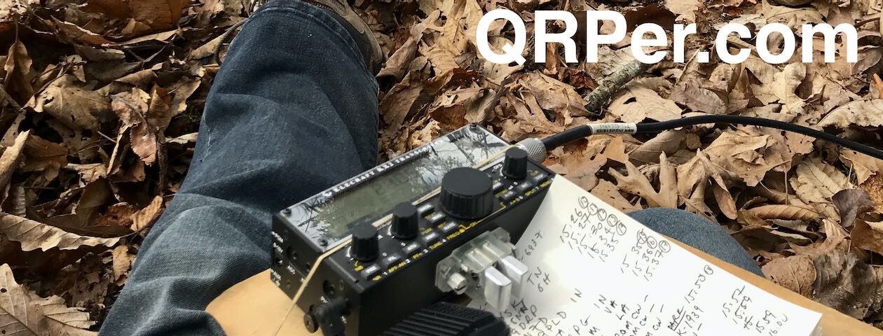
All of our equipment is home-built. It’s evolved over the last year-and-a-half into he tidy kit you see above. Finally having a ‘typical’ kit picture is actually what inspired this article.

Equipment List:

[Please note: All Amazon links are affiliate and support QRPer.com.]

  • Rockmite 20
  • Tuna Topper
  • One 20 ounce can Dole Pineapple Slices (emptied—see support crew; and cleaned)
  • Two RJ-45 breakout boards
  • One spool butcher’s twine (two if you’re feeling bougie)
  • One Imuto power brick that supplies 15 V when funneled through:
  • One Adafruit USB Type C Power Delivery Dummy Breakout – I2C or Fixed – HUSB238
  • Two banana jack sockets (plus a few more for spares)
  • Forty feet 12 gauge insulated/stranded wire
  • Twenty-five feet (or so) RJ-45 Ethernet cable (scavenged from the parts bin at our local maker space)
  • One antenna launcher (scavenged from available fallen tree limbs onsite)
  • One donut Bag from your favorite donut store
  • One roll of washi tape

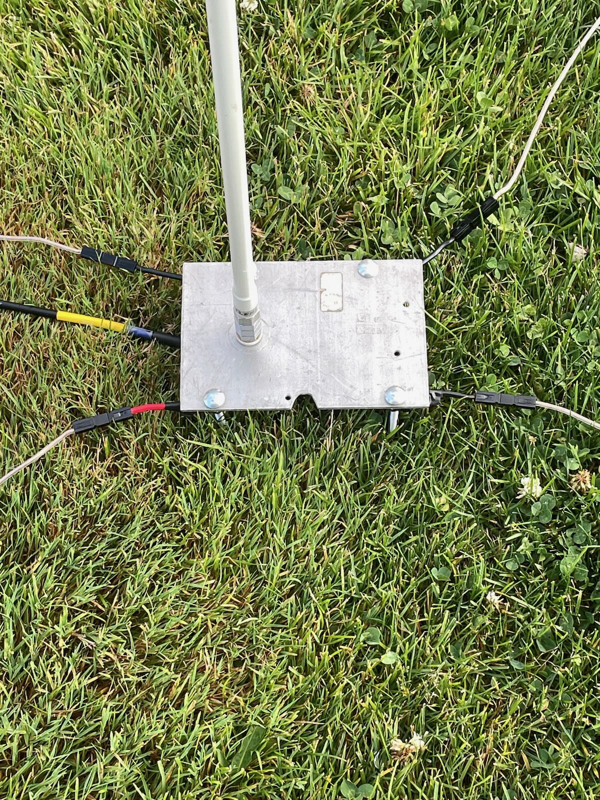
The Rockmite is a rock-locked radio with two available frequencies that are 500 Hz apart from each other. That makes our antenna design really simple; we’ve got a dipole that’s trimmed to be resonant at 14057.5 kHz. Project TouCans puts out a QRP maximum 5 Watts. Our field kit has evolved to that 5 Watts though. We started out with the Flying Rockmite at 250 mW, then we made a power bump to 750 mW, and then with the addition of a Tuna Topper amplifier and a lot of experimenting we finally achieved a QRP maximum 5 Watts output power.

The QRPp Rockmites–having so little power combined with lots of somewhat confusing reading about antenna matchers and coaxial cable and baluns–led to the original Flying Rockmite. “Do you know what makes you not have to discuss feed lines?” I reasoned, “Not having a feedline.” And so, the RockMite was inserted into the dipole. I brought the keyer controls down to me and sent the power up along an Ethernet cable. Continue reading Field Radio Kit Gallery: KD0FNR’s Rockmite 20 and Tuna Topper

BG6LH Designs a Board for Integrated Yaesu FT-817/818 FT8 Operation

Many thanks to Cao (BG6LH) who writes:

Hi, Thomas!

I would like to share my QRP FT8 kit for Field Operation.

A long time ago, I was seeking the most lightweight QRP kits for FT8 field operation. My goal was to have just one radio, one antenna, one phone, without too many cables, boxes, etc.

Finally, I designed a PCB. It is a Bluetooth DIGI Adapter and can be mounted on the rear panel of my FT-818.

Just plug it to the DATA and ACC jacks. It can be powered by ACC jack’s 13.8V Pin.

It works well with FT8CN, an android FT8 app.

Now, my dream has come true!

My Antenna was a so-called GAWANT, designed by JF1QHZ, I guess it’s a simple Vertical EFHW. I built it with a 1.2 meter rod.

It’s working on 7~28MHz bands, not very efficient, but so small and portable.

For FT8 QRP POTA, field operation, all of these components can be put in a small bag, and deployed in minutes.

I shared my PCB design on Github. If anyone wants to modify it, you are welcome to do so!

https://github.com/BG6LH/FT-81x-BT-DIGI-Adaptor

Thank you for sharing this, Cao. This is absolutely amazing and an incredibly clever design! I suspect a lot of FT-818/817 enthusiasts will make this same build via your design!

Thank you for reaching out and for sharing your work with the QRP community! 

BD4LB’s Simple Homemade L-Match for Field Operating

Many thanks to HUAQIANG Gu (BD4LB) who shares the following information about his homemade L-Match. Note that BD4LB doesn’t speak English, and I don’t speak Chinese, so the following was machine-translated via Google Translate:


Homemade L-Match for Field Operating

by HUAQIANG Gu (BD4LB)

L-MATCH has a simple structure and is easy to make.
It is mainly composed of a coil and an adjustable capacitor.

  1. The coil is made of copper wire with a diameter of 1.8mm, and the outer diameter of the coil is 50mm.
  2. The capacitance of the thin film adjustable capacitor is 0pF–200pF.
  3. When using, a balanced ground wire needs to be installed.
    (Different bands, multiple quarter-wave length wires, and together. I use a row of wires. For example: two balanced ground wires 10 meters and 5 meters long, respectively 40 meters band and 20 meters band balanced ground wire.)

After many outdoor communications, I adjusted the end-fed antenna. The length of the radiator was 10 meters, which was appropriate.

One end of it is hung from the top of a 6-meter-long fiberglass fishing rod. On the other end, connect the red binding post of L-match.

Balance the ground wire and connect it to the black binding post. Spread it out on the ground.

The L-match is placed on the ground and connected to the HS1B or KVE60C antenna analyzer using a one meter long 50-3 coaxial cable. (This reduces the length and weight of the coaxial cable.)
When using an inverted V antenna, the length of the coaxial cable needs to be at least 8 meters.

My outdoor communication is mainly on the top of a hill in the park, or on the beach by the sea.

On the beach, there is plenty of space. In addition to setting up end-fed antennas, you can also set up inverted V antennas.

On the top of the mountain in the park, the space is limited, and it is difficult to deploy the 20-meter-long antenna oscillator. Only 10-meter end-fed antennas can be used.

After fixing the fishing rod, installing the antenna radiator and balanced ground wire, first connect the antenna analyzer KVE60C.
Use copper alligator clips to clip on the coil and adjust the adjustable capacitance to minimize the standing wave ratio of 7.023 MHz.
(Change different coil taps, adjust the adjustable capacitor, and try several times.)

I carry a compass to adjust the transmitting direction of the end-fed antenna. I won’t get lost.

The actual communication effect is quite good.

In the 40-meter band, it is suitable for short-distance communication within 800 kilometers.

In the 20-meter band, it is suitable for communication within 1000-2000 kilometers.

Guest Post: Lake Thunderbird (K-2792) with a homebrew transmitter!

Activating (sort of) Lake Thunderbird (K-2792) with a homebrew transmitter

Sam Duwe WN5C

When I dove into radio a couple years ago a few sub-hobbies caught my attention: QRP, portable ops, CW, and homebrew. Of course, these all fit nicely together, but in my mind there was a huge leap between soldering an unun and a building a radio. But why not try? What’s the worst that could happen by melting solder and then sitting at a picnic table? This is how I built a simple transmitter and kind of activated a park.

The Michigan Mighty Mite

Nearly everyone has heard about the Michigan Mighty Mite (MMM), a QRPp transmitter popularized by the Solder Smoke blog. There are countless YouTube videos and posts across the internet. It’s very simple: a single transistor, a variable cap, a coil, a crystal and some resistors and a cap. Supposedly one can get up to half a watt of output (I couldn’t). But with a small purchase from Mouser one can oscillate. That seemed pretty cool.

I hadn’t touched an iron until I started playing radio. But I’ve been drawn to homebrew projects. I built a regenerative receiver last year which was very rewarding. I’ve also put together kits (a QCX mini and a TR-35). But my dream has always been to construct a transmitter/receiver combo, or a transceiver. I thought a good place to start was the MMM.

I built the transmitter based on the common schematic for the 40-meter band. The MMM is crystal controlled but I opted to solder in a socket and buy a handful of crystals, so I have the luxury of operating on 7056, 7040, and 7030 kHz. I made a few other improvements, too. The first was to build a low pass filter to attenuate harmonics. Second, although I haven’t finished it yet, the switch on the right will be to choose between multiple crystals. And third, I added a BNC jack to connect a receiver, with a transmit switch. When not in use the transmitter will dump into a dummy load. This receiver switching idea was lifted from the design of the MMM that QRP Guys produces.

When I tested the transmitter at home the best I could get with my charged Bioenno 3 Ah battery was about 300 mW output. The filter is reducing things somewhat, but maybe I need to look into a different transistor or rewind the coil. But I was able to get a 339 signal report from Illinois (no sked) in the midst of distance lightning crashes, so I had a little confidence going forwards. School is out for me this summer, so I decided to head to the park. Continue reading Guest Post: Lake Thunderbird (K-2792) with a homebrew transmitter!

Steve’s Homebrew Vertical Antenna for POTA

Many thanks to Steve (KM4FLF/VA3FLF) for sharing the following guest post:


A Great Homebrew Vertical Antenna

by Steve (KM4FLF/VA3FLF)

Last spring, I was going through my many boxes of ham “stuff” looking for items to sell at our club tail gate sale. I came across a couple of Hustler SM Series Resonators (20 /40 Meters) that I had acquired. I am not sure where I obtained them, but I decided they were keepers.  That decision turned out to be the first step in a year long process that has given me an awesome homebrew vertical antenna.

After doing a little research I found the resonators and accessories at most of the online ham dealers. They are used primarily as mobile and marine antennas. I had seen where a ham had used these on a ground stake as a portable antenna as well. I ordered a Hustler MO1 mast which is 54 inches tall and thought I would attempt to make a portable POTA antenna.

Antenna base

I had a couple of small aluminum plates that I drilled out a few holes. I cut out a notch to put a SO-239 Stud Mount on the plate as my antenna base. I now had a ground plate, connector, and antenna with resonator. By putting a stake in the bottom of the plate, I was able to get the antenna to stand up. The Hustler resonators have a hex screw for tuning that can be loosened. The antenna can be adjusted for resonance by lengthening or shortening the radiator length. After adjusting the radiator my SWR was still horrible on the two bands.

Antenna base close-up

I had some 14-gauge wire laying around and attached it to the plate using carriage bolts and nuts for my ground radials. I didn’t think about the length of the wires at this point but went with three or four lines around 20 to 30 ft. I was able to use my vertical a few times with moderate success. My SWR on 20 and 40 Meters was around 2:0 to 1 at best. It was bulky and very delicate. Sometimes screwing in or unscrewing the MO1 the SO239 would slide off the edge of the aluminum plate. I put away my contraption for the winter and decided to move on to something else.

In April of this year, I wanted to revisit my project. Continue reading Steve’s Homebrew Vertical Antenna for POTA

Field Report: Let’s build a super simple antenna on-site and activate this park!

Until 2016, I had never purchased a commercial field antenna; I built all the ones I had ever used.

These days, I take a number of commercial antennas to the field and use them in my real-time videos and I really enjoy deploying and using them. My buddy Eric (WD8RIF) reminded me, though, that I hadn’t actually used a homebrew antenna in ages. He was right!

You see, while I believe commercial field antennas can be incredibly durable and compact, it’s important to note that antennas are one of the easiest components of an amateur radio system to build yourself. They require only the most simple of tools and are very affordable. And the best part? They can perform as well as those that are available commercially.

I also get a great deal of pleasure out of building things.

A simple goal

I’ve mentioned in previous posts that I often set a little goal that runs in the back of my mind for each park or summit activation I make.

On Monday, June 14, 2021, I made a simple goal: buy my antenna wire en route to Lake James State Park, build the antenna on site, and complete a valid Parks On The Air (POTA) activation.

A very simple antenna

I also decided to employ my Xiegu X5105 since 1.) it’s one of the most affordable general coverage QRP transceivers I own and 2.) it has a built-in antenna tuner (ATU).

One of the cool things about having an ATU is that, if it has the matching range, you can allow it to do the “heavy lifting” in terms of matching impedance.

Although I’d never put the X5105 to the test, I suspected its internal ATU would have the matching range to forgo building a 4:1 or 9:1 transformer and simply pair it directly with a random wire.

All I would need was a 28.5 foot length of wire for a radiator, at least a 17 foot length for a counterpoise, and a BNC to binding post adapter.

The antenna would benefit from multiple 17′ counterpoises, but I really wanted to keep this setup dead simple to prove that anyone can build an effective field antenna with a very minimum amount of components.

Even though I have plenty of wire lying around the house to build this simple antenna, I wanted to pretend I had none to prove that any wire would work.

And to add just a wee bit more challenge, I also limited myself to shopping for antenna wire between my home and the park without making a serious detour from my route. That really limited my options because there isn’t much in terms of commercial areas between me and Lake James State Park.

The wire

As I left the QTH, I decided that the best spot to shop was a Walmart in Marion, NC. It would only be a four minute round-trip detour at most.  I had a hunch that Walmart would even have speaker wire which would be ideal for this application.

In my head, I imagined I would have at least three or four choices in speaker wire (various gauges and lengths), but turns out I had a difficult time finding some at Walmart. We live in such a Bluetooth world, I suppose there isn’t much demand for it these days. A store associate helped me find the only speaker wire they had which was basically a 100 foot roll of the “premium” stuff for $17 US.

While I would like to have paid a fraction of that, in the end it’s not a bad price because once you separate the two conductors, you have double the amount of wire: 200 feet.

Although the frugal guy in me cringed, I bit the bullet and purchased their speaker wire. To be clear, though, I could have found another source of wire in that Walmart, but I preferred speaker wire for this application. And $17 to (hopefully!) prove a point? That’s a deal! 🙂

Lake James State Park (K-2739)

Once I arrived on site, I found a picnic site I’d used before with some tall trees around it.

Here’s how I prepared the antenna:

First, I cut 28.5 feet of the speaker wire from the roll and split the paired wires so that I’d have two full 28.5 foot lengths.

Next, I stripped the ends of the wire and attached banana jacks I found in my junk drawer. Although these aren’t necessary as the binding post adapter can pair directly with the wire, I though it might make for a cleaner install. In the end, though, I wasn’t pleased with the connection to the radiator, so dispensed with one of the banana jacks on site, and later dispensed with the other one as well. The connection is actually stronger without the banana jacks.

I then deployed the 28.5 radiator with my arborist throw line, and laid the other 28.5 half on the ground (the ground of this antenna would pair with the black binding post, the radiator with the red post).  I only needed 17 feet of counterpoise, but once it couples with the ground, I don’t think any extra length makes a difference (although less than 17 feet likely would).

The antenna was essentially set up as a vertical random wire with one counterpoise.

I then plugged the BNC binding post adapter into the rig, hit the ATU button, and was on the air.

It’s that simple!

My new speaker wire antenna in all its glory.

Gear:

On The Air

I’ll admit: I was a bit nervous putting this antenna on the air. Although I felt the X5105 ATU *should* match this antenna, I had no idea if it actually would.

Fortunately? It did.

At this point, if you don’t want any spoilers, I suggest you watch my real-time, real-life, no-edit, no-ad, video of the entire activation (including buying and building the antenna!).

Click here to watch the video.

Otherwise, scroll for my activation summary…

I was very pleased that the X5105 found a match on the 40 meter band.

I started calling CQ in CW and validated my activation by logging 10 stations in 13 minutes.

Honestly: it doesn’t get much better than this.

I logged three more stations on 40 meters CW, then moved up to the 30 meter band where the X5105 easily found a match.

I worked one station on 30 meters before heading back down to the 40 meter band to do a little SSB. I logged three SSB stations in five minutes.

Mission accomplished!

In the end, I logged a total of 17 stations including a P2P with K4NYM.

Not bad at all for speaker wire!

After the activation, I tested the X5105 ATU by trying to find matches on other bands–I was able to find great matches from 60 meters to 6 meters. Most impressive!

X5105 battery

You might recall that I attempted to deplete my X5105 internal battery at my last (rather long) activation of Lake Norman State Park.  I wasn’t able to deplete the battery at that activation, but I finally did at this one.

All I can say is that I’m incredibly impressed with the X5105 internal battery.  This was my fourth activation from one initial charge on May 16.  The battery lasted for 20 minutes, taking me well beyond the 10 contacts needed to validate this park. I’ll now consider taking the X5105 on a multiple SOTA summit run!

Short Hike

Even thought the heat was intense and the humidity even more intense, I decided to take in a 2 mile hike post-activation. I snapped a few shots along the way.

This is the Christmas Fern which derives its name from a few characteristics: its resilience to early season snows maintaining a dark green color beyond Christmas, and because folks believe its leaves are shaped like Santa’s boots or even Santa on his sleigh.

Improvements

I’ll plan to add more counterpoises to the speaker wire antenna as I know this will only help efficiency.

In addition, I’ll plan to build even more antennas with this roll of speaker wire. If you have some suggestions, feel free to comment!

Thank you for reading this field report!

Cheers,

Thomas (K4SWL)


Do you enjoy QRPer.com?

Please consider supporting us via Patreon or our Coffee Fund!

Your support makes articles like this one possible. Thank you!

Upgrading my Yaesu FT-817 with G7UHN’s rev2 Buddy board

This article was originally published on the  SWLing Post.
Last August, SWLing Post contributor, Andy (G7UHN), shared his homebrew project with us: a genius companion control display for the venerable Yaesu FT-817 general coverage QRP transceiver.

Andy’s article caused me (yes, I blame him) to wax nostalgic about the popular FT-817 transceiver. You see, I owned one of the first production models of the FT-817 in 2001 when I lived in the UK.

At the time, there was nothing like it on the market: a very portable and efficient HF, VHF, UHF, multi-mode general coverage QRP transceiver…all for $670 US.

In 2001? Yeah, Yaesu knocked it out of the ballpark!

In fact, they knocked it out of the ballpark so hard, the radio is still in production two decades later and in demand under the model FT-818.

I sold my FT-817 in 2008 to raise funds for the purchase of an Elecraft KX1, if memory serves. My reasoning? The one thing I disliked about my FT-817 was its tiny front-facing display. When combined with the embedded menus and lack of controls, it could get frustrating at home and in the field.

I mentioned in a previous post that I purchased a used FT-817ND from my buddy, Don, in October, 2020. I do blame Andy for this purchase. Indeed, I hereby declare him an FT-817 enabler!

FT-817 Buddy board

When I told Andy about my ‘817ND purchase, he asked if I’d like to help him test the FT-817 Buddy board versions. How could I refuse?

Andy sent me a prototype of his Version 2 Buddy board which arrived in late November. I had to source out a few bits (an Arduino board, Nokia display, and multi-conductor CAT cable). Andy kindly pre-populated all of the SMD components so I only needed to solder the Arduino board and configure/solder the cable. I did take a lot of care preparing and soldering the cable, making sure there was no unintentional short between the voltage and ground conductors.

Overall, I found the construction and programming pretty straight-forward. It helped that Andy did a remote session with me during the programming process (thanks, OM!). Andy is doing an amazing job with the documentation.

I do love how the board makes it easier to read the frequency and have direct access to important functions without digging through embedded menus. While there’s nothing stopping you from changing the program to suit you, Andy’s done a brilliant job with this since he’s an experienced FT-817 user.

The Nokia display is very well backlit, high contrast, and easy very to read.

“Resistance is futile”

I mentioned on Twitter that, with the backlight on, the FT-817 Buddy makes my ‘817ND look like it was recently assimilated by The Borg.

Don’t tell any Star Trek captains, but I’m good with that.

Andy has a rev3 board in the works and it sports something that will be a game-changer for me in the field: K1EL’s keyer chip!

For more information about the FT-817 Buddy, check out Andy’s website.

Of course, we’ll keep you updated here as well. Many thanks to Andy for taking this project to the next level. No doubt a lot of FT-817 users will benefit from this brilliant project!

Bill’s 1 Watt Wood Box QRP Beacon

Many thanks to Bill (AA0RQ) who writes:

I’m running an attended beacon on 7041.8 kHz–the ID is VVV de AA0RQ/B AA0RQ/B AA0RQ/B 1 watt…

Often after running the beacon I plug the beacon crystal into the little 6L6 single tube transmitter.

Been having a number of QSOs with the bread boarded radio…

Below is the 40 meter 6L6 transmitter:

Thanks for sharing, Bill–I love the wooden box enclosure as it reminds me of early 1900s wooden box homebrew radios.

We’ll be listening for you on 7041.8 kHz!

micro-BITX: a homebrew general coverage SSB/CW QRP transceiver

Image Source: uBITX)

Many thanks to Pete (WB9FLW) who shares the following:

Farhan VU2ESE Does It Again!

http://www.phonestack.com/farhan/ubitx/ubitx.html

A compact 10 watts, easy to build, general coverage SSB/CW transceiver for HF bands

Homebrewers have traditionally avoided making multiband transceivers as they can get extremely complex and difficult to make. There have been some remarkable successes in the past, the CDG2000 (designed by Colin Horrabin G3SBI, Dave Roberts G8KBB and George Fare G3OGQ)is one such design. The SDR route as followed by several designs offer some simplification at the cost of bringing digital signal processing and a PC into the signal path.

On the other hand, many of the homebrewers do need a general coverage transceiver on the bench as well as as a base transceiver for bands beyond the HF. I ended up buying an FT-817ND that has been a reliable old warhorse for years. Two years ago, I attempted a high performance, multi-band architecture with the Minima transceiver. The KISS mixer of the Minima, though a very respectable receiver front-end, had serious leakage of the local oscillator that led that design to be abandoned as a full transceiver. Over months, I have realized that the need for a general coverage HF transceiver was wide-spread among the homebrewers. Most of us end up buying one.

While achieving a competition grade performance from a multiband homebrew is a complex task as evidenced by the works like that of HBR2000 by VE7CA, it is not at all difficult to achieve a more modest design goal with far lesser complexity. The uBITX shoots to fulfill such a need. It is a compact, single board design that covers the entire HF range with a few minor trade-offs. This rig has been in regular use on forty and twenty meters for a few months at VU2ESE. It satisfies for regular work, a few trips to the field as well.

A key challenge for multiband transceivers has been to realize a local oscillator system with such wide range. Silicon Labs has now produced a series of well performing oscillators that solve this challenge trivially : You connect the oscillator chip over a pair of I2C lines and it is done. The Si5351a is one such a part that provides 3 programmable oscillator outputs in a small 10 pin TSSOP package. We will exploit this chip to build the multiband transceiver.

Having exclusively used homebrew transceivers all the time, I get very confused whenever I need to use a commercial radio. There are too many switches, modes and knobs to twirl around. The uBITX use an Arduino to simplify the front panel while retaining all the functionality in a simple menu system that works with the tuning knob and a single ‘function’ button. The rig supports two VFOs, RIT, calibration, CW semi break-in, meter indicator, etc. In future, more software can be added to implement keyer, SWR display, etc.

Click here to read the full description of this project and download diagrams/schematics!

This is brilliant!  Thank you for sharing, Pete!

Ken’s PCB holder makes for a great weekend project

Thanks, Ken (WA4MNT), for bringing this very cool and simple project to our attention.

Click here to download instructions–parts are available from Ken for $23, or components can be home-brewed (I can imagine the plastic components can be replaced with wood).

Check out some of Ken’s other projects at www.qrpbuilder.com.