
For the past couple of weeks, I’ve been playing with end-fed wire antennas. Before I get into the nitty-gritty details, let me first make a distinction between end-fed half-wave antennas, such as the ones sold by LNR Precision and end-fed wires that use some kind of tuning to achieve a 50 Ω output impedance.
End-fed, half-wave antennas (EFHWs) are a half-wavelength long and are resonant antennas on the band of interest. They use some kind of matching network to trasnsform the very high impedance at the end of a half-wave wire to about 50 Ω. Generally, they are not usable on bands for which they are not a half wavelength long. You can’t, for example, generally use a 40m EFHW antenna on 20m.
End-fed wire antennas are a different beast. They are not a half-wavelength long, meaning that, if you choose the length of the radiator wisely, the impedance at the end of the wire will not be as high as the impedance of a half wavelength long wire.
 In many cases, the impedance can be transformed with the help of a 9:1 unun (unbalanced input to unbalanced output). See the figure at right. A 9:1 unun is a transformer that reduces the impedance at the input by a factor of 9. So, if you connect a length of wire that presents an impedance of about 450 Ω to the input, you’ll get an impedance of about 50 Ω on the output.
In fact, the 9:1 unun that I built is actually an autotransformer. Here’s a video that talks a little bit about autotransformers.
It’s relatively easy to build a 9:1 balun. One of the most common designs is to wind nine turns of a trifilar winding around a toroid core. Trifilar means that there are three wires wound simultaneously around the core. I’m not sure why there are nine turns, instead of say eight or ten, but I suspect that it’s a compromise between size and coupling. Nine turns yields sufficient coupling to ensure that the impedance transformation will take place without taking up too much space.
By the way, the ratio 9:1 isn’t really magic. You could choose to build a transformer with 7:1 or 12:1 ratio, but it just so happens that it’s much easier to build a 9:1 transformer than a 12:1 transformer.
 I built one on a T80-2 powdered iron core, using some 22-ga. wire that I scavenged from some four-conductor cable (see photo at left.) I got a little bit lucky in that the T80 core has a diameter just big enough to accommodate nine turns. Using different colored wires (red, black and white) made it easier to wire it up properly.
I didn’t do much engineering when it came to selecting the parts. I just happened to have a little bag of T80-2 cores that I’d purchased cheap at Dayton a couple of years ago. The short length of four-conductor cable was something that I’d salvaged from some previous project and had just thrown into my “wire box.” I haven’t done the calculations, but as built, I’d guess that it’s good up to 25 W or so. If you’re shooting for an unun to handle more power, then go with a T130 core and heavier gauge wire.
There’s also some question about which type of core to use. Some people wind their unun on ferrite cores instead of powered iron cores. One manufacturer even goes so far to say that they use a “custom mix” instead of one of the standard ferrite mixes (although I find it hard to believe at the relatively low quantities that they must be purchasing that they’re getting a truly custom mix). My friend, Thom, W8TAM, built his 9:1 unun using an FT82-61 core, and it works great. G3TXQ has performed a number of experiments with different core types, and with the antenna he used, found Type 2 powdered iron cores to be preferable.
So, how long a wire should you use for the antenna? It really depends on what bands you want to work. Mike, AB3AP, has calculated the lengths that give good results on various bands. Jack, VE3EED (SK), has also made this calculation. They differ slightly because VE3EED used the center of the bands in his calculations, while AB3AP used the center of the CW portion of the bands.
Last Saturday, I played around with an end-fed with a 36-ft. radiator and counterpoises of 13-ft. and 25-ft. To be honest, I wasn’t really happy with any of the configurations. The best I was able to do was achieve an SWR of 2:1 on 40m with the 36-ft. radiator and the 13-ft. counterpoise. Neither configuration yielded a satisfactory match on 20m.
Thom, on the other hand, used his 9:1 unun with a 30-ft. radiator and got fantastic results. He got great signal reports from an NPOTA station, a special event station in Georgia, and an operator working aeronautical mobile over Nebraska. So, there’s more experimentation in my future.
Update 8/19/2016
As I mentioned earlier, I wasn’t very happy with the results I was getting with the 9:1 unun that I had built earlier. So, yesterday evening, I went over to W8TAM’s house to compare his ununs to the one I just built. As I noted above, Thom had great success with his a couple of weeks ago.
The first thing we did was check that I had wired it properly. The only thing that we found is that instead of nine turns, I had only wound eight turns on the T80-2 core. I didn’t think it would make that big a difference, but Thom had a lot of wire, so we rewound the unun, this time making sure that I wound nine turns.
We connected two 1 kΩ resistors in parallel (to give us an input impedance of 500Ω) from input to ground and measured the output impedance on Thom’s Rig Expert AA-170 antenna analyzer. As I suspected, the extra turn made little difference. The SWR was 6.5:1 on 7150 kHz.
(As an aside here, I have to comment on the AA-170 antenna analyzer. In a word, it’s fantastic. One of the functions we used, for example, measures the SWR of antenna at the midpoints of all the amateur bands. This function is just perfect for testing the frequency response of baluns and ununs. It’s also graphs SWR across a frequency range. And, on top of all that, it’s about half the weight of my Palstar antenna analyzer. I think I’m going to dump the Palstar and get a RigExpert.)
At that point, we figured that the only thing it could be was the core. Fortunately, Thom had an FT82-61 ferrite core that he’d used to wind a QRP 9:1 unun. We cut three more lengths of wire, wound the unun, connected the 500 Ω load and measured the SWR.
WOW! The thing worked exactly as predicted! Here are the measurements:
| T80-2 | FT82-61 | |
| 7150 | 6.5 | 1.2 |
| 10125 | 4.1 | 1.1 |
| 14175 | 2.9 | 1.0 |
| 18118 | 2.3 | 1.1 |
| 21225 | 2.0 | 1.2 |
This was very puzzling and aggravating. As I noted above, G3TXQ found that the #2 powdered iron cores gave the best results. After a little Googling, I also found another ham, VK6SYF, who had success with a #2 core (http://vk6ysf.com/unun_9-1.htm). My friend KA8BMA built one using a T106-2 core, and it seems to be working right.
I bought the cores from a reputable dealer, so I don’t think that they’re bad, but I don’t know how else to account for the difference in performance. If you have any ideas on that, I’d love to hear them.
After getting that out of the way, we got into a discusssion of whether or not I really needed a 9:1 unun at all. The two radios that I use for portable operations are the Elecraft KX1 and the Elecraft KX3, both outfitted with antenna tuners. Both of them seem able to tune just about any length of wire not an exact half-wavelength, and that being the case, why bother with the 9:1 unun? The unun would just introduce more loss into the system.
Sounds like more experimentation is in order.
UPDATE 8/22/16
A couple of days ago, I e-mailed G3TXQ about my lack of success building a 9:1 unun with a T80-2 core, even though he seemed to have the best success with a #2 core. He said, “Using #2 cores will not give you a very accurate 9:1 impedance transformation, particularly if you use something as small as T80 size.” I found this kind of puzzling as he had said that in his experiments, he got the best results with a #2 core.
Anyway, since my friend Rich, KA8BMA, had wound his 9:1 unun on a T106-2 core, I thought I’d try this, too, and I just happened to have one in my box o’ toroids Well, wouldn’t you know it, the measurements are much, much better with the T106-2 core than they were with the T80-2 core.The SWR measured 1:1 on 20m and 17m, something like 1.8:1 on 40m, and 1.5:1 on 15m.
The frequency response of this unun isn’t as flat as the unun wound on the ferrite core, but it is certainly much better than the unun wound on the T80 core. The T106 core is only a quarter inch larger in diameter than the T80 core (1.06-in. vs. 0.80-in.). I wouldn’t have thought that a quarter-inch in diameter would make that much difference, but it did.
In researching this further, I discovered why. According to VK2TIP’s explanation of wide-band RF transformers, the impedance of the primary winding should be at least fives times the input impedance. Since my test input impedance is 500 Ω, that means the impedance of my primary winding should be at least 2500 Ω.
Using the online calculator at toroids.info, at a frequency of 14 MHz, and a primary winding of 27 turns, I get the following values:
| AL | Ω | |
| T80-2 | 5.5 | 352.7 |
| T106-2 | 13.5 | 865.7 |
| FT82-61 | 79 | 5066 |
The first thing to notice is that the inductance factor, AL, for the T-106-2 core is nearly twice that for the T80-2 core. I erroneously thought that they would be the same since the core material was the same. The higher value yields a higher inductance, and therefore, a better transformer.
Even so, the inductance is far from five times the input impedance. That’s why the FT82-61 ferrite core works much better for this application. With an AL of 79, the primary has an impedance of more than 5000 Ω, which gives a very good transformation.
As Steve, G3TXQ, pointed out in his e-mails to me, it really doesn’t matter if the impedance transformation is exactly 9:1 or some other value—especially if you will also be using an antenna tuner. In that case, winding your unun on a T106-2 core—or even better a T157-2 core that has an AL of 14—will work OK. If you’re like me, though, and want a 9:1 unun to actually give you a 9:1 transformation over most of the HF bands, then use a ferrite core.
One final note: A very nice feature of the toroids.info calculator is that it not only calculates the impedance for a particular number of windings, but also the length of the wire that you’ll need. On my first attempt at winding an unun on a T106-2 core, I greatly underestimated how much wire I needed and ended up throwing away that wire. I could have avoided doing that if I’d used the calculator.
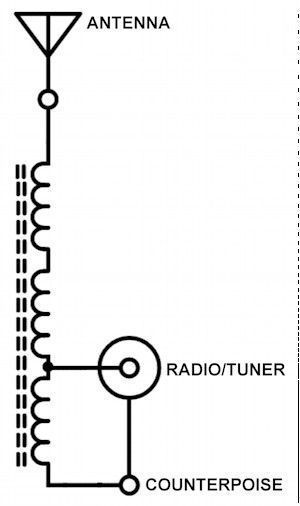
Actually, the 9:1 ratio is kind of magic, because 9 is the square of an integer.
Your unun has integral numbers of turns in its primary (9 turns between the counterpoise and the radio tap) and an integral number of turns in the secondary (27 turns between the counterpoise and the antenna with 9 of the turns common to both primary and secondary). That makes the secondary voltage 3 times the primary and the secondary current 1/3 of the primary — 3 being the turns ratio. That makes the secondary impedance (voltage over current) 9 times the primary impedance since the factor of 3 shows up as a multiplier of the secondary voltage and a divisor of the secondary current. In other words, the impedance ratio is the square of the turns ratio.
So to wind an unun with an impedance ratio of 7 or 12, you’d need to wind a transformer (or autotransformer) with a lot more turns in order to approximate ratios of the square roots of 7 or 12 — roots that are not integers. If you’re using a trifilar winding you’re going to end up with an autotransformer with turns ratios of 3:1 or 3:2 depending on where you put the tap for the radio, or a transformer with a 2:1 ratio if you connect only two of the winding in series and isolate the third winding,
With a quadrifilar winding, a 16:1 impedance ratio would be straightforward.
Larry K8MU
Thanks..shared with the QRP group https://www.facebook.com/groups/qrpradio/
Mike WG7D
Hi Mike, good to see U off Face book
Actually, an EFHW for 40M can be used on 10M, 15M, and 20M as well.
Four Lakes Amateur Radio Club, W9JZ, in Madison, WI used 2 of the EFHW-8010 antennas into quadplexers for 15/20/40/80 for ARRL FD this past June. Since we were using quadplexers to feed 3 rigs, we could not use tuners.
http://myantennas.com/wp/product/efhw-8010/
Theoretically, this is an end-fed half-wavelength antenna only on 80m. On 40m, 130-ft. is about one wavelength, so the impedance at the ends should be quite different from the impedance at the end on 80m.
The QST review notes that the matching unit is just a 49:1 transformer (7:1 turns ratio), so it’s kind of amazing that the SWR would be so low on 40m. It would be interesting to build one and connect a 130-ft. piece of wire to it. You could certainly build one for a lot less than 150 bucks!
Maybe you should revise some of your statements in this blog post because they reflect great misunderstanding how most multiband antennas work including EFHW end fed antenna. For example, in your following text you claim : quote
“End-fed, half-wave antennas (EFHWs) are a half-wavelength long and are resonant antennas on the band of interest. They use some kind of matching network to trasnsform the very high impedance at the end of a half-wave wire to about 50 Ω. Generally, they are not usable on bands for which they are not a half wavelength long. You can’t, for example, generally use a 40m EFHW antenna on 20m.” end of quote
It is wrong to claim that EFHW for 40m can’t be used on 20m, by that logic you can’t use OCF Dipole (“Windom”) for 40m on 20m too, in fact they are the same antenna with different position of feed point.
Also, feed point impedance on end of the half wave radiator is very close to 1 wave length, 1 and 1/2 wave length, 2 wave length etc. Difference is minute and only impacted by height above the ground. In general it is between 2000-3000 Ohms.
73 Danny N4EXA aka E73M
The Par End-Fedz web site states no ground plane or counterpoise is needed.
Paul KW1L
There is a counterpoise. It’s the shield of the coax you use to connect the antenna to your rig!
hi Dan,
I use the Par tri band end fed QRP antenna and use no coax. using a double male connector I hook it directly into my LDG qrp auto tuner and it works fantastic for me… Normally use the antenna helically wound around a 31 foot mfj pole or in a sloper configuration is the trees cooperate
73bob
But I have with a field strength meter proved there is more radiated power with a counterpoise or radial system, Also grounding one to the tower at the top using the tower as a counterpoise worked even better than no ground as per a field strength meter! Wx9dx
I wound an 9:1 unun last week on T200-2 core with 18 awg enameled wire. I didn’t have a suitable box so this week is a trip to the hardware store at some point.
http://www.eham.net/ehamforum/smf/index.php/topic,76839.0.html
You W8JI should talk, you can get alot of his postings at eham
I’d just like to know why wind 9 turns? I’ve seen 8, 9, & 10 turn unun designs. I’ve also seen 4 turn ferrite designs.
My guess is that somewhere along the line someone thought that nine turns sounded like a good number, or nine turns is all that would fit on the core they had, and so they built their unun with nine turns. That worked, so it’s been nine ever since. To be honest, I wound ten turns on the T106-2 core. It sounds like the more turns, the merrier you’ll be.
Hello Dan,
My unun have 13 turns, is ok 3,5mhz to 28 mhz.
73
Saulo
PY7EG
Question. I’ve been told that one cannot use an antenna tuner on an endfed antenna with a 9:1 unun installed. Could someone please explain. New Ham here.
I’m not sure why they’d tell you that. I connected mine to my KX3, and then used the internal antenna tuner.
Mine is also connected to an autotuner, either the one in my TS590SG or an LDG200. It works very well!
I also use a remote tuner that connects to a 9:1 unun that feeds an EFHW wire for 75 meters. The only band I have trouble tuning is 17, where the SWR is 2.5:1. I may experiment with shortening the wire a bit to improve 17. It’s also marginally usable for 6 meters.
I’ve been using a 9:1 autoformer wound on a red color toroid with 27 turns of a single wire with a tap at 9 turns. I put a 140 pF polyvaricon across the total turns. I can get low SWR for my QRP/SOTA operations on 40, 30, 20, and 15m with my 24 1/2 ft. end-fed wire.
I wonder if there is any advantage to wind a 9:1 as a single winding or bifilar or trifilar. Anyone know about this?
My guess would be that the differences between using a single winding, a bifilar winding, or a trifilar winding would be minimal, but that’s only a guess. Might I suggest that you make up a single-winding version and run a test?
Dan,
I ordered an EARCHI 9:1 Balun kit, and am going to play with it. The tri-filar windings make no sense to me. It’s a transformer, and the only one that makes sense is VE7BPO’s, where he used an FT-114-43 toroid, with 33 turns on one side, and 11 turns on the other. That’s 3:1 turns, and 9:1 impedance. Tri-filar can do this how? Baluns, ununs, they make my head spin…
Im trying to use the MFJ EFHW that is supposed to work 10 thru 40. All bands work great except 40 which even the internal turner cant fix. UGH !
I have a 50 foot counterpoise and I havent tried to trim it as of yet.
Think that would help ?
The length of the radiator and the counterpoise, and how they’re positioned will all affect the impedance at the feed point. I think that the first thing that I’d try is changing the length of the radiator. Tack a couple feet of wire onto the end and see what happens. Also, experiment with the length of the counter poise. To shorten the counterpoise, just roll it up a few feet.
I have been using a 9-1 unun, no ideas on the colour or type, but was assured that the length of 60ft in any configuration and at least 16.5 of coax used as the counterpoise will work. I have tried different lengths and configurations. 35ft loosely coiled around a 6m pole in a vertical configurations gets me into the far end of Europe on 5watts. Mostly with a 59 report. Let’s be honest, it’s not a beam antenna on a tower, but it’s working the same people in Europe as the people with a beam. A little devil insides really giggling at those who spent a wheelbarrow full of money on that beam and tower. Sorry chaps, but it had to be said. Some people like to fly fish, other prefer a harpoon.
I’d like to build an antenna like the one you describe: what material do you use for the pole? What size wire?
Well, you want to use something non-conductive for the pole. Lots of guys use telescoping fiberglass masts. The size wire depends on how much power you’ll be running. If you’re not running a lot of power, you can use a small-gage wire.
I have no idea why you vuys are playing with ununs and calculators. After years of listening to
All the gobbly gook and being scared off to try I took the info from an old 1940s hand book and built a 1/2 wave single wire end fed antenna for my vintage stack. Right from the first time I lit it up it work far better then I ever expected. I use it on 40m as well. Swr on my meter is less then significant even with no tuner. Results are excellant. Good enough that now after 10 years or so I have no desire for anything else. In my opinion you lads are over complicating a very simple and effective antenna system. I had had many antennas over the years . Beams phased arrays verticals and dipoles of every discription (in verted Vees . Trafitional dipoles and even fan dipoles) At this QTH the simple end fed longwire has been by far the most effective.
I have built 4:1 and 9:1 ununs that are on toroid forms and wound them trifilar on pieces of PVC tubing. The ones on a red toroid seem to work better on 160M and above 12M but they all work well. In fact, they rune with my FT-450AT internal tuner although they test to be under 3:1 SWR-wise and usually less than 2:1, depending on the band being tested. However, there are some test results for the EF antennas that I have found useful.
My system uses the 53-ft length on the main radiating element. I have tried 66-ft and it does not work as well as the 53-ft length here. This is a variable length that requires some experimentation. Some get away with less but some require more length. The counterpoise is 16-ft long and the main element and counterpoise are suspended as a dipole. However, the main thing I found is that the feedline must be dressed a certain way. I first tried just letting it hand down but it was horrible, Then I pulled it back under the counterpoise and the feedline is 45-degrees down from the counterpoise.
Another item is that there is about 20-ft of feedline between the 9:1 unun and a 1:1 balun. This coax is also part of the counterpoise/other end of the antenna. The 1:1 balun is a ferrite bead balun and I wonder if an “ugly balun” would work as well. I suspect that it would for some but not for all depending on the location where the antenna is used. Surrounding structures (the metal farm) also has some bearing on these kinds of antennas.
The unun is a copy of the EARCHI kit that I got from W4KGH who duplicated the EARCHI kit. He would have to be contacted to get details on ordering the kit. ([email protected])
One note is that the first contact I made with this antenna was on 160M…!
Bob — KK5R
I agree with Don LYX. After messing around with loaded verticals, shorty dipoles, etc the best antenna I ever had was an endfed longwire, about 60 foot long made out of lamp cord. They can be touchy to tune up but they do get the signal out. I homebrewed an EARCHI antenna and while it does kind of work, it isn’t something I would like to depend on to make it across the country. To be fair, the designer never billed this antenna as a DX wire so our expectations may be somewhat misplaced. Bottom line is, if it works for you, fantastic! But I’ve also seen guys working 40m with a cb groundplane too, so there ya go! …73, Jay N3DQU
Here we see HAMS missing the point altogether with science rather than experimenting. 48 years of doing this stuff as a kid, Navy tech and real engineer, stateside and overseas for three countries. The theory and the math are well know, The blogs saturated with wanna-be engineers. But the point is building a detailed, by-the-book antenna will always have issues, whereas stringing a wire and tuning it up often gives the HAM what he/she wants most – getting on the air. Enjoy the hobby, but if it turns out to be work beyond a few simple equations and theory decades old, you are not going to relax and have fun. In reality, the 9::1 works well for endfeds and so does a 50 ohm coax connected to the end of the wire. The real problem is whether you can cover the entire range of HAM frequencies and/or within each band with a reasonable SWR. Try 203 feet of wire and a 9::1 balun with a tuner other than your radio’s. Never had a problem with the wire being suspended at least 40′ up on military fiberglass poles at the ends of my yards at various US sites ranging from MA, DC, SC, to OH. IF it feels and sounds like work, then it is not a hobby-it is just work to fill the time your real job does not.
As a professional engineer, I get paid big bucks to grind the math, and I don’t need it after hours when I am not taking long-haired stuff back from the office, or 12 hours working DoD systems. Have some fun people !!!
Bravo! I QRP and play with cheap antennas, often without good theory or math. My best successes have been devoid of both.
After tearing apart my OCFD in a tree on a QRP outting I opted to load up the metal roof of the pavilion working it against a cast iron BBQ grill. I worked 40m and 20m in quick succession with my FT-817d from Merritt Island, FL to Sarasota, FL and to Kansas City, Kansas.
I ended up here looking at end fed wires to operate from my 1st floor condo. I have two loops. On 1/2 wave at 40m and the other an MFJ Magloop. One is noisy. The other very narrow and sensetive to neighboring metal when tuning. It’s time to play different, again.
Thank You. I’m very new to the hobby and it’s sometimes overwhelming to be inundated with so many formulas. I just need a simple card with easy to understand formulas and diagrams that are tried and true and I’ll do the rest
What makes you think that the folks on here discussing variations and trying them out, are not having fun? One of the hallmarks of ham radio is experimentation. Just because it may require some work certainly does not disqualify it as a hobby. It’s also safe to say that most hams are not engineers, nor is it a prerequisite to enjoy the hobby or to make a workable amateur station.
Stephen Slater G0PQB- I use a 24ft 6in vertical wire portable with an FT817 and an LDG Z817. On 5 watts I have worked Asiatic Russia and heard stations in Bhutan, Japan, all round the US, Africa and Europe. I used the same antenna at home and worked all round the US, Canada, Brazil, all round Russia and Asia and Africa. Yes it does work and works well and I am very happy with the 9:1 system.
For portable work the whole thing can be erected in less than five minutes. There’s five of us who go out portable and use this system for all bands from 6m to 40m.
The proof of the pudding etc etc.
Hi –
With the 24.5 wire and 9:1 unun, how long was your counterpoise? I assume the feeding coax is the counterpoise? Did you use a 1:1 isolator also, at some point upstream from the 9:1?
thx, de WX8V
Good evening Steven,
I have been doing extensive research to find the correct length of wire to use with my 9:1 unun matchbox transformer. Hopefully this will give me an edge for when skywave propagation conditions are. I’m not using an amplifier due to living in a HOA residential community and don’t have any tree’s. Will try to mount it as high as I can to see how well it gets out.
Where on cw or ssb?
Any help would be greatly appreciated.
Well the old rigs used tubes which unlike semiconductor devices which need the Swr at 50 ohms don’t go pop at the slightest mismatch.
1)Anything will radiate, so put it up and give it a try. People have worked the world loading rain gutters, light bulbs.
2)The magic sauces in core selection is loss at a frequency and power handling, which are described in the manufacturer’s data sheet. Google is your friend here. The bigger the core, and the higher the permeability, the fewer turns are needed for an inductance.
3) A good reference for multiwave wire antennas is Terman’s “Radio Engineer’s Handbook”. The math is minimized and there are a lot of charts. There are a lot of early 1940’s copies for sale cheap as it was passed out to communications gus in WWII. You can also download PDF’s of it from several websites.
4) LCDR Yuna is right- keep it fun.
Thanks for the build out infotmation and more i portantly the lessons learned. The coax feedline is key to great performance.
I wish more people would go out into the wild with a 9:1 balun and recommended length(s) of wire and also a resonant end fed half wave (EFHW) using a 64:1 type transformer and correct wire lengths for either a 40-10m or 80-10m version. The 9:1 will make contacts but can also light up the coax with hot RF. When switching to the resonant EFHW you will notice signal reports will soar on all resonant bands and you will then realize what a dog the 9:1 types are like the EARCHI. There is virtually no difference in cost or complexity making a 9:1 vs 64:1 transformer, so I and many others are puzzled why people still bother to make a 9:1 type when the resonant EFHW with a 64:1 or 49:1 type transformer is so far superior on the air. The resonant EFHW types do not light up the coax with RF unless you operate them way out of band. I’ve made quite a few 64:1 transformers on a tiny FT-114A-43 core that will handle 100w SSB and it fits into a box slightly bigger than a Zippo lighter. Couple that with about 64ft of #22 wire tied to 40ft of small guy string and all that fits inside a plastic chalk line reel for the ultimate portable HF antenna. In addition to making several 64:1 type transformers of all sizes and power levels I also purchased a 2kW rated one from Danny at MyAntenas and am very pleased with its quality and performance for full legal limit use.
My question is .. I would like to build a 9.1 endfed. Could buy one . But want to build one With all the toroid’s which one would be good for say 200 watts .
Iv’e watch a lot of video’s But haven’t found my answer.
I just did a little research myself on this. I have an LDG RBA 4:1 balun, so I cracked it open. It’s rated at 200 W and uses and the instruction manual says that it uses an FT-125 toroid. It doesn’t say what mix the ferrite is, but -61 or -43 are usually good choices for HF baluns. Kits and Parts doesn’t sell FT-125 toroids, but they do sell FT-140 toroids, which are a little bigger, and should actually handle a little more power. Their price for two FT140-43 toroids is $5. The price for two FT140-61 toroids is $6.
I hope that helps!
For those wondering about 9:1 trifilar windings you need to take a step back to the days of dirigables filled with hydrogen gas and the fact they had no “earth”. Look up the zepp(lin) antenna. It uses two wire feeder both as an impeadence transformation and to provide a counterpoise for the matching transformer resonator “to work against”.
The simple fact is for a transformer of any type to work (and this includes balans and ununs etc) to get current from one output port the other output port has to have the same current… To expect otherwise would be “magic thinking”. Thus you need a couterpoise and banging a nail in the ground will just warm up the earth not get it to radiate so you have a massive loss if you do not have a counterpoise. In no way should the counterpoise be in contact with the earth it needs to be around 3ft to 20ft off of the ground depending on frequency to get the best radiation. If you don’t have a counterpoise then the current from the second output port will find a way to radiate or earth via capacitive or inductive coupling. The result will be “hot feeders” to the rig and it’s earth which might well be through the operator. Anoying with QRP but how about with 1.5KW? RF burns don’t heal well…
So think zepp solution, you don’t need to use two wire feeder to get the counterpoise and it does not need to be a quaterwave or even resonant. If you want the best radiation you want to use a choke balun (beads along the coax) into a balun / issolating / link / transformer to bring the antenna resistive component into the correct match (reactive match in ATU). After this transfromer you then need a bifilar current balancing balan which then drives the antenna and counterpoise. The feed line between the ATU and resistive component matching transformer should be as short as possible. The coax from the ATU to the rig can then be any length you like with only losses being your concern. You do not need to earth the rig except for “electrical safety” and if you are doing this but another string of beads choke balun on the feed line immediatly at the antenna connector of the rig.
For those doing QRP SOTA style where earths are impractical you will find that this alows you to put maximum RF into the air. To improve things, changing the length of the counterpoise as part of the tuning proceadure will give you the best radiation you are likely to get with an end fed wire be it random or some supposed resonant length.
Back to that 9:1 trifilar, 50 x 9 gives you 450 and 75 x 9 gives you 675 which just happen to be common impedences of two wire feeders as used in zepp antennas (and J-poles). As for trifilar winding it has the effect of turning the transformer into a transmission line transformer which increases the bandwidth at the upper end. To further increase the bandwidth at the lower end put a 1-5KV rated 100-250pF capacitor across the primary. If you are going to use resonant halfwaves then use a 64:1 transformer it prowides a more stable thus more easily tuned load.
Speaking of resonant antennas, few if any antennas will be resonant at 50R therefore 1:1 SWR = Resonance is a falsehood more times than it is not. As real old timers will tell you forget resonance forget SWR you need to tune for maximum antenna current. With Tubes/valves this used not to be a problem as they were more gracefull under mismatch. Modern semiconducter finalls whilst designed to drive maximum power into a 50R load are most certainly not 50R output (if you think otherwise if they were then they would disipate 50% of the DC in power). Thus they use transformer based impedence matching which means unless your antenna is purely resistive it will require (lossless) reactance matching which means you need an ATU which almost without exception should be as close to the reactive load as possible.
For QRP work you can use a 64:1 impedance transformer and then with a good quality variable capacitor bring it into resonance with the endfed wire.
This is all “old knowledge” but few appear to remember it and why. Oh and have a hunt for multiband zepp antennas in the L configuration they realy do work well, you just need an extra “not grounded” counterpoise wire running from the open feeder transformer (second output port) under the antenna wire around a meter off the ground. You will need to adjust it’s length by “bunching the end up” as you change from band to band but it will mean that around 95% of your power will get radiated not 80-90% warming the ground. So worth the marginal extra effort when working SOTA or /alternative/portable or even stationary mobile.
I’m a recent convert to the end-fed antenna. I panicked when I found out when Field Day was, so I snap-ordered an MFJ-1984MP antenna. While it didn’t arrive in time, I have it now and am experimenting. I installed it about 6 feet off the ground from the side of my house to a point on the fence 66′ away. Result: far quieter than my vertical, so DX is louder, and I have had contacts with ZL stations and all over Europe fairly regularly on 100 watts. MFJ claimed you wouldn’t need a tuner in most cases. For me, that’s correct. 40-10 (no WARC), it’s essentially flat. I’m sold. I”m going to build more, just because they’re easy, cheap, portable and get the job done.
For a Ham Radio guy its hard to believe you thought 8 loops would not make THAT much of a difference ……
Dont agree on your statement on the EFHW. My half wave on 40 has a low swr there and on 20 and 15, Many others I have read are finding the same thing. My 20 mtr. swr is not as low as I plan on getting it but it is very useable. My Antenna expert shows the results in the freq. plots I have done.
Could I ask what length of radiator you’re using on 20m? I’m trying to put together a tuner-free 20m QRP EFHWA, but information on radiator length is hard to come by. (One source suggests 84 feet. Seems improbable for a wavelength that tops out at ca. 66…)
It would be particularly useful to know how much wire I should start with, before trimming it back for lowest SWR.
Thanks!
33’ is 1/2 wave on 20m.
I am have very good luck making my own 9:1 ununs using, of all things, salvaged ferrite beads from computer cables. Since their makeup varies with their original application, I pair them up, binocular style and check using 8 loops of wire and measure impedance. If it comes in at 200uH or less their suitable. I’m talking for use on 20 and 10. you can only get so many turns of #20 vinyl hookup wire thru them. For the primary, it’s one turn or loop thru the cores. For the secondary, i found 3 and a half turns to be optimum. While camping and just some wire strung up in a tree, I was able to obtain SWR readings very close to 1-1 with no tuner needed! With my 706 I was able to make several contacts in the conus, Hawaii and Canada on 20. For 40 and 80, anther primary winding is necessary, with the commensurate increase in secondary turns. This means larger beads, like the FB102-43. They will handle more power as well. I’m finding a good enclosure to be a pair of 1″ PVC end caps with thin wall pipe connecting them. One of them needs a flat bottom to mount an SO-239 connector. The other just a stud and wingnut. Very cost effective I must say. In fact, I’m going into production! I’ve already salvaged several bead pairs that are suitable. I’ve been able to find dozens of stray cables at thrifts stores and the like.
“You can’t, for example, generally use a 40m EFHW antenna on 20m.”
Yes, you can. 20m is a harmonic of 40m, and a 49:1 auto transformer will bring it to a low swr on both bands. You use a 9:1 on a random wire antenna, not on an EFHW.
84 feet (with a 17ft counterpoise) is a good length for a NON-resonant (“random wire”) antenna. For a EFHW (note that HW = Half Wave; just like a center-fed dipole), start with the usual 468/frequency in MHz.
Hi All.
Starting to play with end-fed I have 4 questions.
1. I want to feed my antenna from a variable link coupling tank of a very old TX I am restoring (2×812’s). I believe the output Z will be about 450 Ohm Balanced (Barker & Williamson). The EF antenna Z is about 250 Ohm Unbalanced. a 2:1 ratio? If correct, can someone give me some info on the construction i.e toroids, winding Etc.
On another project, I want to couple that same TX to a ladder line feeder. (450ohm)
Here I will need a 1:1 transformer, right? I need the same help.
3. Operating the EFA as a vertical. you opinions, please.
4. and the last, In several discussions writers are pointing out to the necessity of using a choke to avoid the line to become radiant. What say you? And how to build one?
Thanks in advance to all responders.and 73’s
Ira Curtis CE3AM
60+ years of Hamming
Hi, have an homebrew end fed antenna just want to ask if I use 12m pole where is the ideal location of the balun should it be on top of the mast and run the wire vertically to ground or balun near the ground and run the end of the wire top of the mast.
Jhun,
“where is the ideal location of the balun”
With an “end fed halfwave” where you use a voltage transformer it is most convenient for the earth / counterpoise side of the transformer secondary usage.
The point you should worry about hight wise, is where the “high current” is in the antenna. With a halfwave this is at it’s lowest impedence point which is in the middle of the antenna where you would normally feed a halfwave dipole with a current balan to stop current coming back down the outer of the coax.
Thus an End Fed Halfwave supported at the middle on a fishing pole etc gives you an inverted V configuration you would keep the angle more than 90degrees and preferably greater than 120degrees with the ends of the wire being atleast four foot of the ground.
A word of caution needs to be said here, the ends of a halfwave are high impedence and vary from 800-5000 ohms depending on the thickness of the wire using V = sqr(PxR) it does not take much to realise that the voltage on the ends of a halfwave are realy quite high, thus represent not just a danger to humans and animals, but can also be a fire hazard with corona quite capable of jumping several inches.
As a rough rule of thumb counterpoises should be kept not just off the ground but their ends lifted (they too have a voltage problem). A counterpoise hight of “1 inch per meter of wavelength” is about right with the ends lifted about one and a half to two times that hight works best. Thus your voltage transformer should be around six feet of the ground if possible, with a current choke or balan to stop RF going back down the coax outer to the rig and causing problems like a “hot rig”. Whilst for portable QRP you can use the coax as a counterpoise that implies using a long run of it with it’s attendent losses even with a good VSWR at the voltage transformer. Thus I would choke the coax at the transformer of good quality and as short a run of coax as possible to your rig, thus you can get away with very short runs of RG174 which has a lot of physical advantages if you are going on foot to your chosen location.
For a bit of definitive reading on Zepp antennas and building EFHW a useful link is:
https://www.nonstopsystems.com/radio/frank_radio_antenna_multiband_end-fed.htm#half-size
For an interesting video series on making and testing baluns Four installments in the “TRX Bench” series on YouTube start with:
https://www.youtube.com/watch?v=kMlKfHHR8FY&list=PLeeTJyMD2EsnZXWu_C6Zj7IOqqKXSLMxd&index=7&t=0s
These are simply and slowly explained and construction methods and measurements demonstrated – quite long so be patient – shows a lot of useful pricinples.
There are plenty of YouTube videos about making 49:1 or 64:1 EFHW transformers .
Happy reading/viewing
Alan
G8IPQ
I’ve proved that used with a radial system, counterpoise or even connected to a top of a tower for grounding is better on a field strength meter. With a half wave on 40 meters from a 9:1 diy unun. Wx9dx ,Jimmy
Not hooking one to a tower when the tower is right there is costing you radiated power!
For many of us, the nerdy physics details *are* one of the points of being a ham. I went from mildly interested in amateur radio to nearly obsessed when I started looking into antennas that would get me what I want in my tiny backyard. Stringing up more than 10-15 meters (33-50ft) of wire at home is an impossible dream for a lot of people, so we’ve got to make the most of the little space we have available.
Very entertaining! LOL
If you are using a atu why would you need a un-un (balun) why not just use your atu and a long wire around 148 ft. Its going to work. I do qrp and thats all i use and i get out all around the world. ?? Simple and easy radio, atu, wire thats all. Thank you all for your time.