Thursday, February 17, 2011

The 10-meter "Hentenna" loop


clip_image002

This clever little antenna developed by JElDEU of Sagamihara City, Japan. Local hams were amused by the loop; hence the name - "hen" means curious in Japanese. "Henantenna" was quickly shortened to "Hentenna." It's shown in Figure 1. This antenna's virtue is that it has very little "wingspread"

The array has two one-sixth wave radiators separated vertically by a half wavelength. To feed them, connect the tips and tap the vertical wires with a coax feedline. Polarization is horizontal. Hentenna construction is simple. You use a single mast; try a TV-style pushup one. Make your horizontal sections out of 518-inch diameter aluminum tubing bolted to a mounting plate, and attach the plate to the mast with Ubolts. Use enamel-coated copper wire for the antenna's vertical sections. Feed the Hentenna with a balun and coax line. Run your feed wires from the balun to the vertical wires. Adjust for lowest SWR by moving the feed wires up or down the vertical wires. Copper alligator clips are ideal for this; you can remove them and make joint solders when you find the correct points. The points should be about 36 inches above the bottom tube for 10 meters. The Hentenna provides a figure eight pattern at right angles to the antenna plane. Gain is estimated at about 2.5 dB over a dipole. Bandwidth is very broad. By changing the length of the vertical wires, you can move the design frequency to any point in the 10-meter band.

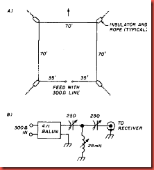
Receiving loop antenna for 160 meters


clip_image002

Height of loop above ground is 10 feet. Illustration A is view from above. Illustration B shows 4:l balun and antenna tuner.

One of the problems in working DX on 160 meters is the high level of background noise. Many DXers have found that they cannot use their transmitting antenna for reception - the noise level is overpowering. Paul McClure, KDBSO, met this problem head on and evolved a horizontal receiving loop that provides good signal-to noise ratio. The loop's signal pickup isn't as good as that of a larger antenna, but noise drops off sharply. By adjusting audio gain of the receiver, you can bring the resulting signal up to the original level. Paul says that, out of the noise, he can pull weak signals that didn't seem to exist under normal circumstances. He says the antenna is comparable to a good Beverage wire. The loop, however, takes up less space and there are no terminating resistors to replace after a thunderstorm. The above-ground height of the loop is about 10 feet. It's fed with a random length of 300-ohm ribbon line. Paul twists the line to balance it to ground.

The bi-square array for 18 MHz


clip_image002

The diamond-shaped bi-square beam is much larger than the delta loop, but provides about 3-dB gain. This is a great antenna to try if you have the space. It's shown in fig. The loop is a half wavelength on a side and open at the top. The feedpoint impedance at the bottom of the loop is about 2900 ohms; I use a twowire 600-ohm quarter-wave stub to provide a more reasonable impedance value of about 122 ohms. Match it to a 50-ohm coax line by adding a quarter-wave transformer made of 75- ohm coax. Wind the 75-ohm line into a coil about 6 inches in diameter to reduce RF currents flowing on the out-side of the coax. Resonate the loop and stub to 18.1 MHz with a dip meter. Temporarily close the stub at the bottom using a movable short with a I-turn loop in the middle.

"Quickie" antennas for 18 MHz


clip_image002

The delta loop in fig. 1 is a good 18 MHz "first" antenna, It has slight gain over di-pole and user friendly

The feedpoint impedance of the loop is about 120 ohms .Use a 75-ohm quarter-wave transformer to provide a reasonable match to a 50-ohm coax line. The transformer is wound into a coil to choke off RF currents that might flow on the outside of the coax shield.

clip_image004

The feedpoint of the loop terminates in an SO-239 coax connector mounted on a small insulator plate. The transformer has PL-259 plugs on both ends. Make the splice between the transformer and the 50-ohm line with a PL- 258 splice adapter. After making the connection, weatherproof the plugs and adapter with coax tape or heat shrink tubing. The loop is supported at the apex and the side insulators are tied off to objects nearby. The radiation pattern is similar to that of a dipole and is horizontally polarized.

The 1.8-MHz inverted L.


Overall wire length is 165 to 175 ft. The variable capacitor has a maximum capacitance of 500 to 800 pF.

clip_image002

The antenna shown in Fig is simple and easy to construct. It is a good antenna for the beginner or the experienced1.8 MHz DXer. Because the overall electrical length is greater than 1/4 ë, the feedpoint resistance is on the order of 50 Ù, with an inductive reactance. That reactance is canceled by a series capacitor, which for power levels up to the legal limit can be a air-variable capacitor with a voltage rating of 1500 V. Adjust antenna length and variable capacitor for lowest SWR. A yardarm or a length of line attached to a tower can be used to support the vertical section of the antenna. (Keep the inverted L as far from the tower as is practical. Certain combinations of tower height and Yagi top loading can interact severely with the Inverted-L antenna—a 70-ft tower and a 5-element Yagi, for example.) For best results the vertical section should be as long as possible. A good ground system is necessary for good results.

Portable 3 element 2M beam antenna


clip_image002

In April 1993 QST, Nathan Loucks, WB0CMT, described the 2-m beam shown in Fig. The boom and mast are made from 3/4-inch PVC plumber’s pipe. The three pieces of PVC pipe are held together with a PVC T joint and secured by screws. Elements can be made from brass brazing or hobby rods. (If you can’t find a 40-inch rod for the reflector, you can solder wire extensions to obtain the full length.)

Drill holes that provide a snug fit to the elements approximately 1/4 inch or so from the boom ends. Epoxy the director and reflector in place after entering them in these holes. A pair of holes spaced 1/4 inch and centered 16 inches from the reflector hold the two-piece driven element. The short ends of

the element halves should extend about 1/4 inch through the boom. Solder the 50-Ù feed line to the driven element as shown in Fig

Loucks used a pair of 4-inch pieces held in place by #12 or #14 jam screws (electrical connectors) toextend and adjust the driven element to allow for operation in various parts of the 2-m band. You can trim the driven element to length for operation in the desired portion of the band if you prefer. The figures show the beam assembled for vertical polarization. You may want to turn the boom pieces 90° for horizontal polarization for SSB or CW operation.

10-m rectangular loop antenna.


clip_image002[1]

With the large number of operators and wide availability of inexpensive, single-band radios, the 10-m band could well become the hangout for local ragchewers that it was before the advent of 2-m FM, even at a low point in the solar cycle.

This simple antenna provides gain over a dipole or inverted V. It is a resonant loop with a particular shape. It provides 2.1dB gain over a dipole at low radiation angles when mounted well above ground. The antenna is simple to feed— no matching network is necessary. When fed with 50-Ù coax, the SWR is close to 1:1 at the design frequency, and is less than 2:1 from 28.0-28.8 MHz for an antenna resonant at 28.4 MHz.

The antenna is made from #12 AWG wire (see Fig ) and is fed at the center of the bottom wire. Coil the coax into a few turns near the feedpoint to provide a simple balun. A coil diameter of about a foot will work fine. You can support the antenna on a mast with spreaders made of bamboo, fiberglass,

wood, PVC or other nonconducting material. You can also use aluminum tubing both for support and conductors, but you’ll have to readjust the antenna dimensions for resonance. This rectangular loop has two advantages over a resonant square loop. First, a square loop has just 1.1 dB gain over a

dipole. This is a power increase of only 29%. Second, the input impedance of a square loop is about 125 W. You must use a matching network to feed a square loop with 50-Ù coax. The rectangular loop achieves gain by compressing its radiation pattern in the elevation plane. The azimuth plane pattern is slightly wider than that of a dipole (it’s about the same as that of an inverted V). A broad pattern is an advantage for a general- purpose, fixed antenna. The rectangular loop provides a

bidirectional gain over a broad azimuth region. Mount the loop as high as possible. To provide 1.7 dB gain at low angles over an inverted V, the top wire must be at least 30 ft high. The loop will work at lower heights, but its gain advantage disappears. For example, at 20 ft the loop provides the same gain at low angles as an inverted V.

A Quick and Simple 2 Meter Ground Plane Project!

If you are just getting experience in building antennas or you are an old pro,here is a simple and fun project! This antenna is perfect for those hams living in the primary coverage area of the repeater for 2 meter use. This antenna is nothing more than the old standby "Droopy Groundplane" and can be used on any band where it's physical size does not pose a problem. Remember that the vertical radiator is 1/4 wavelength long at your operating frequency.

It has no gain but makes an excellent small antenna that can be mounted just about anywhere and with a little planning, can be used mobile on a short mast from the bumper!! Adding a small attachment loop at the tip of the radiator will enable it to be suspended from above for inside use.

The vertical element and radials can be made of #12 copper wire or welding rods, coat hanger, etc. The vertical radiator (A) should be soldered to the center connector of the SO239.The four base radials (B & C) and (D & E) can be soldered or bolted to the SO239 mounting holes using 4-40 hardware. The four base radials then should be bent downward to a 45 degree angle.

The antenna can be mounted by clamping the PL259 to a mast or even passing the coax through a 3/4 ID PVC pipe and compression clamping the PL259. Either way let your creativity work for you. If you plan on mounting it outside,  apply RTV or sealant around the center pin and PL259, and TAPE WELL,  to keep water out of the coax.

Make each radial a 1/4 wave of your desired xmit frequency. Sometimes it helps to add a little extra length to the radials and radiator. This will give you some adjusting room when you adjust the SWR.(If adjustment is needed, clip all radials equally about 1/8 inch at a time while checking SWR, USING LOW POWER). Center the lowest swr on your transmit operating frequency.

Example Calculation:

Freq (mhz)       146
A (inches)         19 5/16 (Note "A" length is to the SO-239 insulator but not critical)

B THRU E (INCHES)   20 3/16

LENGTHS FROM FORMULA ( 234/FREQ MHZ) + 5 % LONGER FOR RADIALS
TRY ONE ON 440 or other bands USING SAME FORMULA AND CONSTRUCTION TECHNIQUES!

ENJOY AND EXPERIMENT!

DON'T TRY IT ON 75 METERS MOBILE......IT' A LITTLE LONG FOR MOST BRIDGES, OVERPASSES, POWER LINES ETC!!!!

simple antenna for 40 Meters


Making a simple antenna for 40 Meters is not very difficult. That is, if you have the space. A standard center fed dipole dipole for 40 Meters needs around 67 Feet of space. But, what if you only have space for a 20 Meter dipole, 33 Feet? If this is case, than you have several options.

  1. You could just forget about 40 Meters and work the higher frequency bands, 20 Meters on up.

    What? And miss out on all the fun dodging the the short wave broadcasters in the evening.

  2. You could create a Inverted-V type of antenna and raise the feedpoint on a mast.

    This is a possible alternative, but for this particular case, you would need a 28 Foot center mast and the apex angle would be less than optimum. This may cause some signal cancelation and give you a radiation pattern that you don't want.

  3. You could shorten the dipole arms to fit the space and use a loading/matching coil in the center.

Item number 3 is what this page is about. Jact Sobel, W5VM (which is now assigned to Vernon Dyer), had at one time described a shortened dipole center fed with a loading/matching coil at the feed point. A drawing of which is below.

Initially, this seems to be a different approach than the shortened dipole designs, detailed on my Short Dipole page. But it's really not. If you tilt your head, and cross your eyes a little bit, you might start seeing it as two coils, very close together. In fact, the coils are so close to the center, that they touch..

Assuming that the two coils are an equal number of turns, and that the wires attached to each side are equal in length, the center of an antenna should be a zero current point. this makes a handy place to tie your coax shield. You could wrap several turns of wire around the coil in the center and feed it that way. But I couldn't begin to tell you how many turns to use or what the feed impedance would be. Each turn of the coil, as you move away from center, provides you with a different impedance and a possible match. By attaching the center of your coax to one of the coils turns, you should be able to find a good 50 Ohm feed point. This then gets around the balanced to unbalanced conversion effort (balun), that would be required and you were center feeding or link feeding..

Each element arm is 18 Feet 6 Inches (5.029 M) long. The loading/matching coils consists of 30 turns of 12 SWG enamelled copper wire wound on 2.5 inch (63.5 mm) diameter PVC tube 6 inches (152.4 mm) long. The winding pitch should be about 6 turns-per-inch (25.4 mm). Although the picture doesn't show it very well, the shield of the 50 coaxial cable is connected to the center of the coil. The coax center conductor is connected to a point 2 or 3 turns away from the center, to a point which gives the lowest SWR. This point may take some experimenting, depending on which section of the band you wish to operate in.

Making a slim jim


made one of thease on me foundation course thease are the smae plans we used.slim jim using both 300 and 450 Ohm Feeder and have found the 450 feeder to be easier to SWR..

TO swr the Slim jim simply hang the antenna in free space away from metal objects and make sure the Coax runs straight down below the antenna.Then simply move the feed point up or down slightly until best swr is achieved..
.

The slim jim is Basicaly a Half wave vertical with a quarter wave matching stub so you can calculatefor any band by simply working out a halve wave length for the Longestlenghth, 468/f in mhz,and for the quarter wave length 234/f in mhz and answers in feet.To match simply adjust the feed point as on the 2m version.also worth consideration is the J-POLE seen below

A Slim Jim for 4m


This antenna is made from a length of 300-ohm ribbon cable, which makes it easily portable, but you have to devise some method of suspending it!  The dimensions quoted in the diagram have been used successfully by some constructors, whilst others have found it to be off-frequency by a few megahertz. This may be due to a parasitic capacitance in the gap between the half-wave and quarter-wave sections, so be prepared to experiment a bit..

Dimensions of 4m Slim Jim.

2 Meter Slim Jim antenna using 300 Ohm Twinlead


300Ohm slim jim antenna diagram plan

Due to popular searches, I’ve included a diagram to make a flexible slim jim antenna. This antenna is useful to increase the range of your portable radio or as a simple QRP mobile antenna for emergency situation.

Basic Slim Jim conceptual plan

In order to proceed with this project you need

  • about 165 cm (64 inch) 300 Ohm twinlead cable
  • RG-58 coax cable (RG-8, RG-213 might be too big for soldering), any length but keep it shorter than 7 meters for portable radio
  • Soldering iron
  • Wire cutter
  • Connector to your Rig (usually BNC type or UHF Male)
  • insulating tape

This is an ideal antenna for first timers to build. It is powerful yet simple to construct, once you get the hang of it you would certainly have no problem to construct other variants of Slim Jim antenna using different material.

This exercise would also prepare you in the world of Amateur Radio where real hams homebrew their own antennas.

Important Notes

  • Make sure you solder the center conductor to the longest part of the antenna, and the outer conductor (braid) at the shorter side of the antenna
  • If you use this on mobile rig, keep transmission power lower than 50watt to avoid the antenna from being burned away.
  • Make sure the antenna is held straight for best transmission and reception. Best way to make sure of that is to hang the antenna at a higher place or strap it to PVC pipe or other non-conductive pole

Advantages of 300ohm Twinlead Slim Jim Antenna

  1. Easy to construct
  2. Has radiation angle almost parallel to the ground which makes your transmission goes farther than 5/8 or ground plane antennas
  3. Wideband
  4. Portable; Easy to carry, store and deployed
  5. Can be use during emergency situation
  6. Light and flexible

Moxon Antenna Plan for 27MHz CB and Freeband Operation


Here’s another 11 meter Moxon Antenna plan suitable for 27MHz CB, Freeband and lower 28MHz Amateur Radio operation band.

10 meter moxon

27MHz CB Moxon Antenna

Dimensions
A- 392.09 cm (154 3/8 inch)
B- 58.62 cm (23 1/16 inch)
C- 11.25 cm (4 7/16 inch)
D- 73.4 cm (28 7/8 inch)
E- 143.27 cm (56 7/16)

Gain, Radiation Pattern (mounted at approx 30feet)

Gain : Approx 10-11dBi (30 feet above the ground)
Freq range : 27.300 MHz – 28.300 MHz


>11 meter 27MHz CB Homebrew Moxon Antenna

The main advantage of Moxon rectangle antenna are :

  • Compact and Small
  • Has considerable gain
  • It can eliminate noise on HF band
  • Easy to construct
  • Suitable for HF operation (mid-low radiation angle)

Refer here for 10 meter Moxon Antenna Plan for Amateur Radio operation (28.2MHz-28.8MHz) : 10 Meter Band Compact directional antenna, Moxon

Hamradio Homebrew 2 Meter Square Dipole Plan


Here is a plan for homebrewing a 2 Meter Square Dipole plan. The advantage of this antenna is that it is unidirectional, and it takes less space than the regular 2 meter dipole. The calculation included on the diagram below is for building the antenna using copper tubing, you should use MMANA-GAL or other antenna simulation software to come up with new dimension for other materials (aluminium, wire, etc).

2 meter square dipole plan

2 meter square dipole plan

Click on the diagram to enlarge it. Hopefully this will help you in brewing new antennas! Original plan taken from KOFF website

VHF or UHF Yagi BALUN Calculator.


For the VHF/UHF frequencies, a 4:1 impedance ratio coaxial balun is normally used. Two sections of identical coaxial cable are needed. One section (A) has a convenient length to reach between the antenna and the transmitter.  Its characteristic impedance is Z.

The other section (B) is a half-wavelength long at the center of the frequency of interest.
The "physical" length is found from: 5904/F = L.  The complete formula is:
        L = 5904 * V/ F  in MHz
where;
L is the cable length, in inches F is the operating frequency, in megahertz
V is the velocity factor of the coaxial cable. 
The result is found by multiplying L by V.
To find the "Electrical" length, divide this result by F.
The velocity factors of common coaxial cables are shown in the following table.
Coaxial cable velocity factors
Regular polyethylene 0.66
Polyethylene foam 0.80
Teflon 0.72
4-1balun-vhf

Both radio signals and light travel almost 300,000,000 meters (186,363 miles) per second.

When designing a matching or phasing BALUN for a VHF or UHF Yagi, the quarter wave transformer is where these calculations will come to life.   Most coax cables we use in HAM radio have varying velocity factors (VF).  That is; RF signals travel at different speeds through these coaxial cables, depending on the cable type we use.   For example, the coax cable you are using has a velocity factor of .80%.  This indicates that the electrical length is actually 80 percent of of its "free space length".  When making a VHF or UHF BALUN or phasing transformer we must be sure we have included the velocity factor in our computations.

Slim Jim (J Integrated Match J-Pole)

 Slim Jim (J Integrated Match J-Pole) is probably the most easiest and powerful 2 meter antenna to build provided you have the exact measurement and material to build it.

This how to will show you how to build a 2 meter slim jim antenna from ordinary insulated copper wire commonly used for carrying AC (alternate current) electricity in your household.

Slim Jim construction basic
I am not only going show you the measurement of slim jim antenna for specific frequency, but I’m going to show you how to calculate slim jim antenna by your own using the basic formula below.

Basic Slim Jim Idea

The figure above shows that the longest side of slim jim is 3/4 wavelength long and the shorter side of the slim jim consist of 1/2 wavelength and 1/4 wavelength long seperated by a gap.

The feedline (coax cable) is normally connected 1/20 wavelength from the bottom of the slim jim antenna with the center conductor connected to the longest side and the shield/braid is connected to the shorter side.

Building the Slim Jim antenna
This guide assume you want to build a slim jim antenna that centered on 146MHz.

Calculation
The formula for calculating wavelength in metric system is 300/(freq MHz)

Using the formula from the figure, we have :

300/146 = 2.055 M
Wavelength = 205.5 cm

Wavelength x copper wire velocity factor = 205.5 cm x 0.94
= 193.17 cm

3/4 wavelength = 193.17 x 0.75
= 144.88 cm (57″)

1/2 wavelength = 193.17 x 0.5
= 96.585 cm (38″)

1/4 wavelength minus gap = 193.17 x 0.25 – 2.6 cm
= 45.69 cm (18″)

Coax tap = 193.17 x 1/20
= 9.6 cm (3 3/4″)

Building Materials

  • 3/4″ diameter PVC (20mm) – 6 feet (180 cm)
  • ordinary insulated copper wire for carrying altenate current (AC) – 11 feet (3.40 meter)
  • Cable ties

Tools

  • Soldering iron
  • Glue gun
  • Somthing to make a hole on PVC pipe

Wire Slim Jim Building Steps

  • First take the PVC pile and measure it according to the 3/4 wavelength formula above (144.88 cm).
  • Make two holes at the opposite side of the pipe. This hole is used for putting the copper wire through the pipe. Repeat this step 144.88 cm away from the top hole. Both of these holes will hold the copper wire.
  • Insert the wire through the hole until both end reaches each other on one side of the PVC pipe. Then measure the length of the wire and cut the wire on that side so the setup resembles the figure above.
  • Cut the wire insulation (but leave the wire uncut) 1/20 wavelength away (9.6 cm) from the bottom of the PVC pipe, again refer the figure above.
  • Solder the center of the coax cable at the longest side of the slim jim (3/4 wavelength part) and the braid/shield at the shorted part of the antenna.
  • Test the antenna using SWR meter to ensure that its SWR is at minimum or within acceptable level.
  • There you go, you’ve build yourself your own 2 meter Omnidirectional Slim Jim antenna for less than USD2 (RM 6.00)

2 Meter Wire Slim Jim Antenna in action

wire_slimjim.jpg

mypapit homebrew 2 meter slim jim

http://please.name.my/111/howto-2-meter-slim-jim-antenna-from-ordinary-wires.html

The 2 meter Omni Samurai Antenna

image

Homebrew 2 meter Amateur Radio Antenna from Ordinary TV Rabbit Ears antenna


Short on a good and reliable antenna for your amateur radio operation ?

Here’s how to make a simple 2 meter amateur radio antenna from ordinary tv antenna (Rabbit Ears Antenna).

Ham Radio 2 Meter Dipole Rabbit Ears Antenna

For your information these antenna can be bought from local tv store at around RM4 a piece (less than USD2).

2 Meter Rabbit Ears dipole

The best thing about these antenna that it has terminating point (screw) which you can screw in your coax cable to each dipole leg, as shown in the (rather blurry) photo.

DIY Amateur Radio 2 Meter TV Rabbit ear antenna

After that, extend the telescoping element to the desired length to match your transmitting frequency.

Vertical Polarised Dipole Ham Radio

Usually amateur radio operator working on 2 meter VHF would use antenna with vertical polarisation. In this case, you need to spread the dipole to vertical position like pictured above, connect it to your transceiver and be amaze by its transmitting (or receiving) power.

Main Advantage of This Antenna

  1. Embarassingly easy to construct
  2. Lightweight
  3. Can be adjusted to any frequency, because of its adjustable telescopic element

As you can see, the rabbit ear tv antenna can also make a good antenna during emergency situation. Its adjustable telescopic elements made it easy to reconfigure the antenna to transmit on different frequencies.

ps : You can use this dipole calculator, if you unsure about the dipole length.

http://please.name.my/105/simple-2-meter-amateur-radio-antenna-from-ordinary-tv-rabbit-ears-antenna.html