Having recently received my new (2nd hand) short contest callsign I was keen to air it and with probably the biggest contest in the world, CQ WW SSB, coming up I decided I would try a single band entry and build a moxon that was as lightweight as possible to use after how well my 50MHz moxon performed for me.
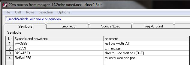
First step was the trusty Moxgen application and give it the wire size to get my start dimensions. As with the 50MHz moxon I then used 4NEC2 to recalculate the sizes for insulated wire as I was using.
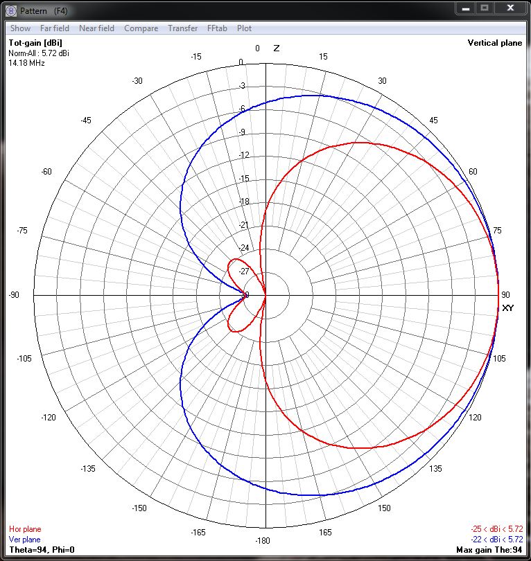
This gave me this predicted radiation plot:
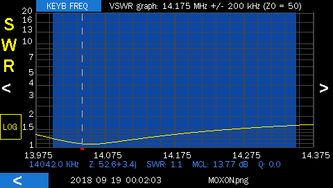
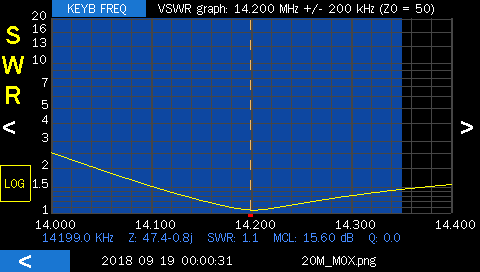
And an expected SWR curve like this:

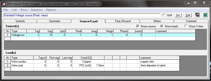
Here is my NEC file for those wanting to work on their own version:
G1YBB_20m_Wire_Moxon.zip
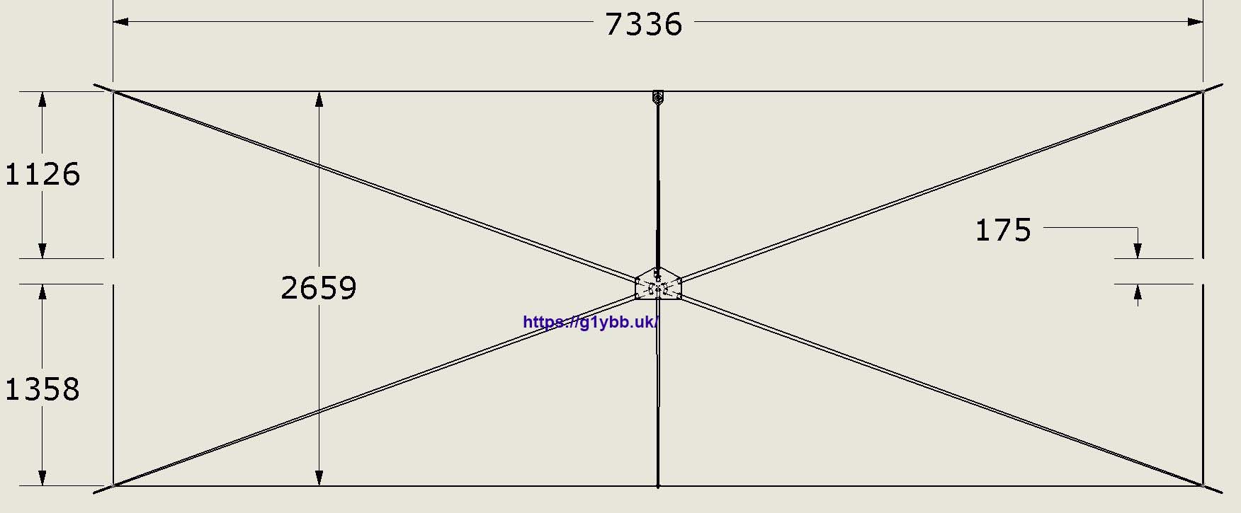
Here are the calculated dimensions above applied to the 3D design described below. Note these dimensions apply to 16AWG/1.5mm2 tri rated wire. Other wire sizes with different insulation thicknesses will be different.
Once I had the dimensions I modelled up the wires in Solidworks to work out how long the spreader poles would be. This turned out to be about 4m so I ordered from eBay two types of 5m long fishing poles for evaluation. To do so I weighed a known length of the wire I was using to get an approximate weight each spreader would support and used something that weight to test how much sag there would be. The windjammer style pole had a thicker top section and was best.
Once chosen I could model up the poles themselves, weigh them and set their weight correctly in Solidworks.
To make the hub, rather than a thick metal plate and chunky U bolts and something to stop those U bolts crushing the poles I decided to use lightweight 1.5mm thick sheets of aluminium in a sandwich arrangement using 3D printed parts to grip the fishing poles without crushing them. I am a big believer in ferrite chokes at the feed point so I wanted a smaller support arm for that also. After my ultralight cobweb build which was unbalanced due to its 5th arm for the feedbox and choke I also wanted this antenna to be balanced, particularly as I intended to use this on the top section of my fibreglass push up mast which is 23mm in diameter.
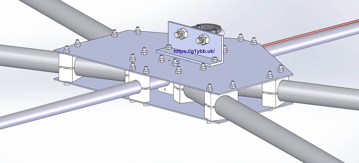
Solidworks is great because it will also tell you the centre of gravity of your design, which I used to find the best places to put the boom supports on my yagi designs. So I was able to see how lop sided the design was, which was quite a bit. A ferrite toroid with coax wound around it on the end of a pole is a fair imbalance. To counter this I moved the mounting point towards the feed point so the main weight could help counter it. There was still a lot of imbalance so I decided there would have to be a support for the reflector to help counter the feed arm and it would also keep the reflector in better shape in the wind. Still not enough and I didn’t want to increase the aluminium plate sizes. Hmm. So I made a wire guide for the reflector support (exactly like the ones for the spreaders) but used a relatively fat chunky M6 bolt and washers for the mass and that pretty much balanced it according to Solidworks.
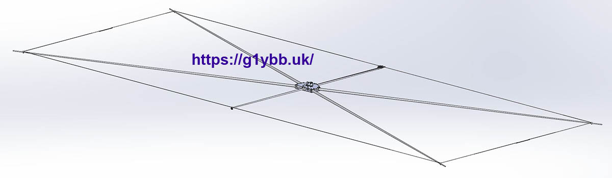
The pink two way arrow shows the expected centre of gravity:
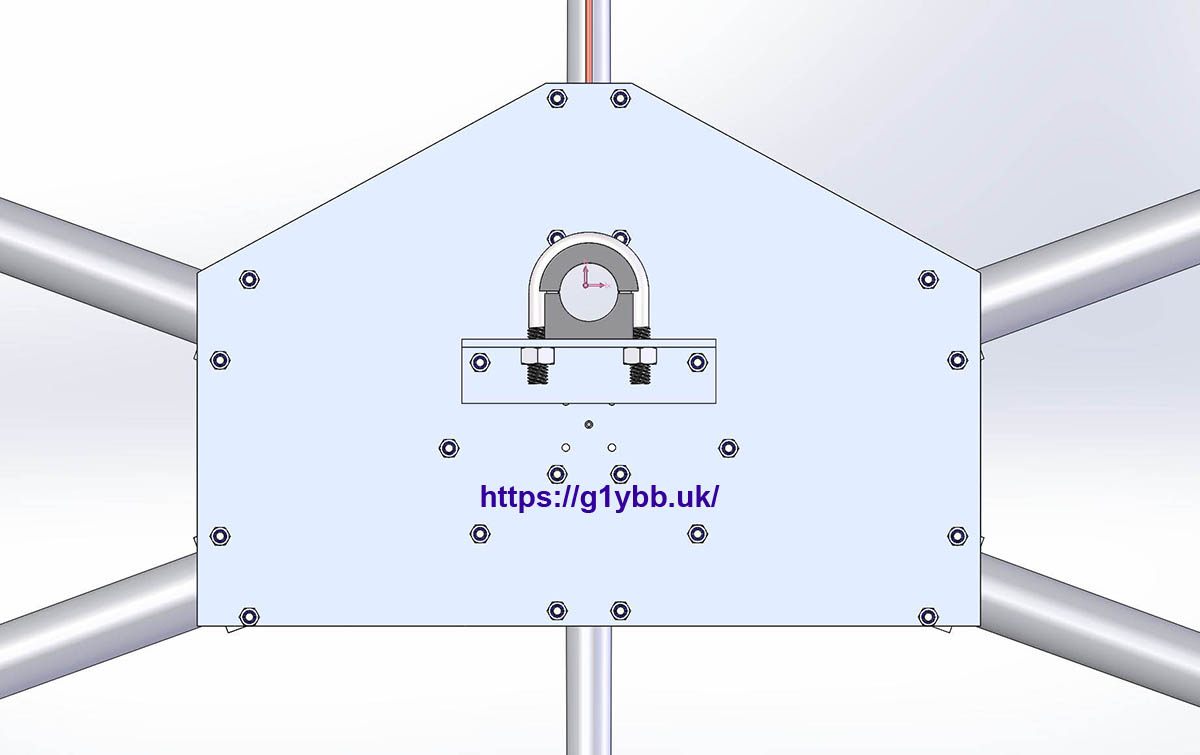
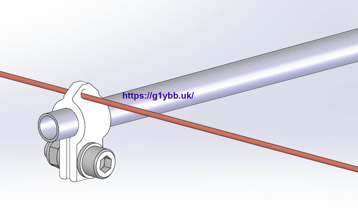
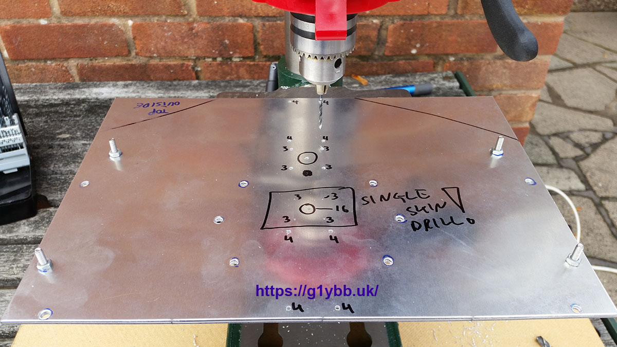
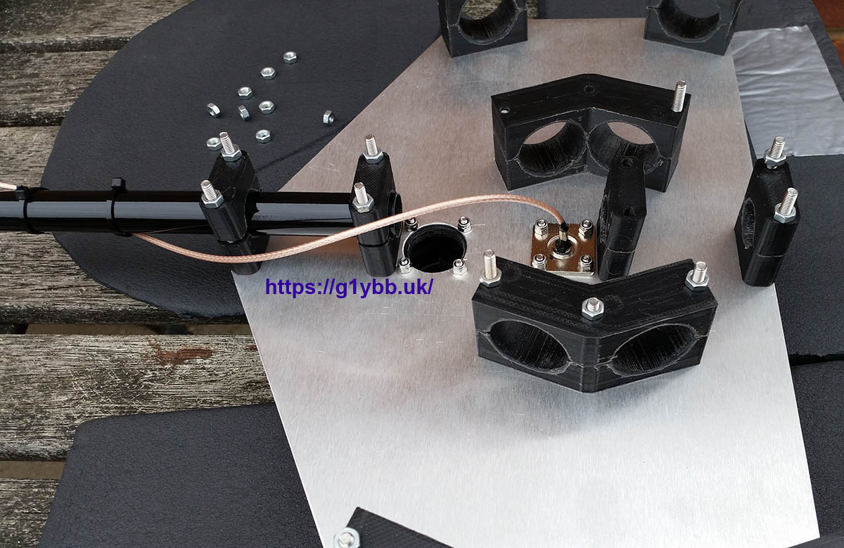
One beauty of 3D printing is you can make exactly what you need so I could make pole clamps the exact size for the fishing poles and also arrange the poles compactly together (needed for the balancing) that you couldn’t do with something like Stauff clamps. I was also able to save on a bolt per side, every little helps. I started with the main pole clamps so I could test if my thin sheet sandwich would work as expected. As the holes were all in odd locations I decided I would mark out by printing a 1:1 scale print of the 3D model of the plate and taping it to one of the sheets and centre marking the holes ready for drilling. I then taped then G clamped the two plates together to drill the holes exactly in the same place on both plates. The holes in the plates are 4.0mm and so are the holes in the 3D printed parts. All the M4 bolts fitted perfectly.
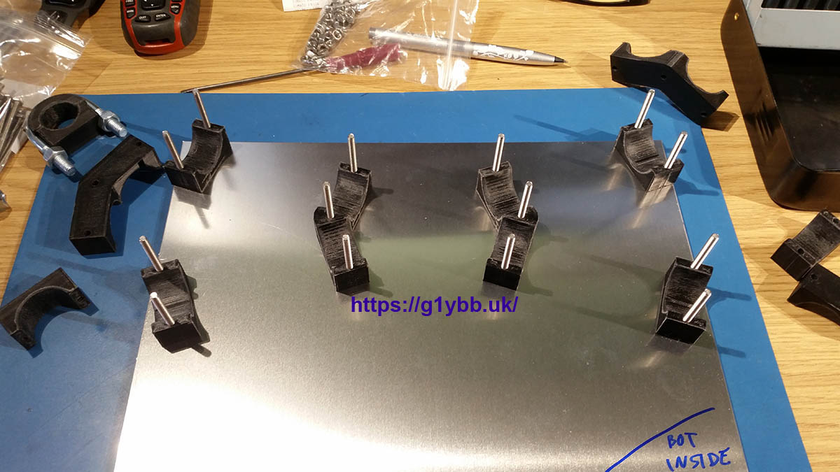
I assembled the poles on and gave the assembly shake. All seemed OK.
I was able to press on with the design and printing. To mount the antenna to a 23mm fibreglass pole without crushing it I got some 32mm U bolts and printed some load spreading clamp halves. Also I was able to print some stiff but light supports to join the ends of dipole halves. Pretty much had a full kit of parts.

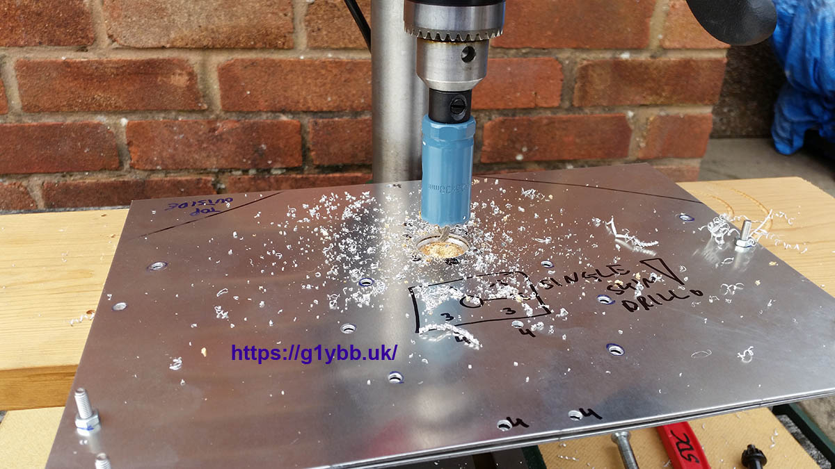
Final drilling could now take place.
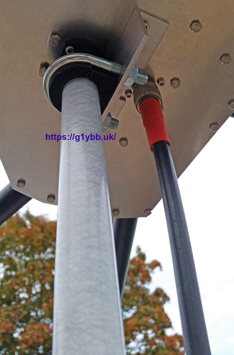
I did a test fit to the pole to ensure it fitted OK:
To connect the feeder I used a panel mount N type socket. I used RG316 to go to the feed point as it’s lighter than RG58,can handle more power being PTFE based and also being PTFE based can be soldered without it melting. I drew up and printed a plate for the feed point with holes to stress receive the dipole wires, slots for cable ties and clamping on the back to attach to the support arm.
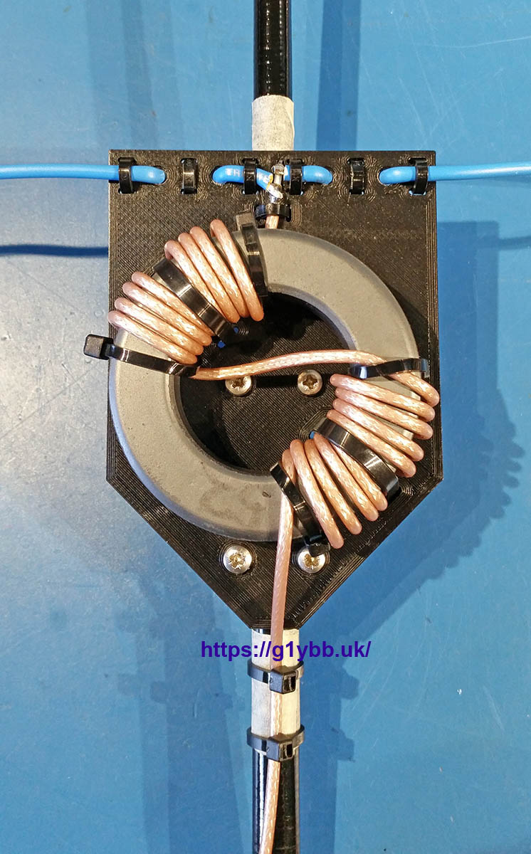
Even though it’s “only” 14MHz I still like to keep the connections tidy.
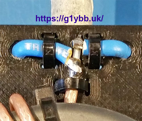
The coax part done I can start final assembly. The N type socket had to be fitted first as it would be very awkward once built.
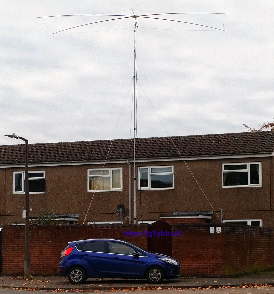
Once mechanically assembled I took it out the front of house to have enough room to rig up the wires. I allowed an extra 20mm on each end to allow for tuning. Another good thing about a full 3D model is I was able to fit my 3D printed wire guides tot he spreaders using measurements taken off the 3D model and as seen below all was spot on.
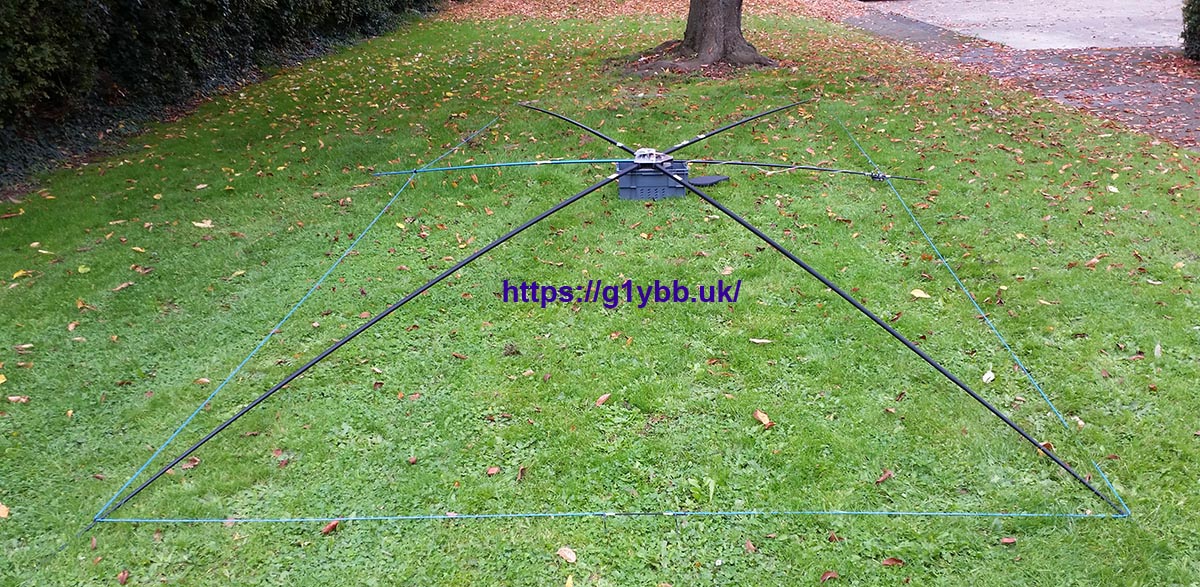
I collapsed the poles to carry it round into the back garden to fit to the mast. Once all re-extended the first thing I wanted to do was check the balance by extending the 23mm section fully to see if it leaned over. Looks good!
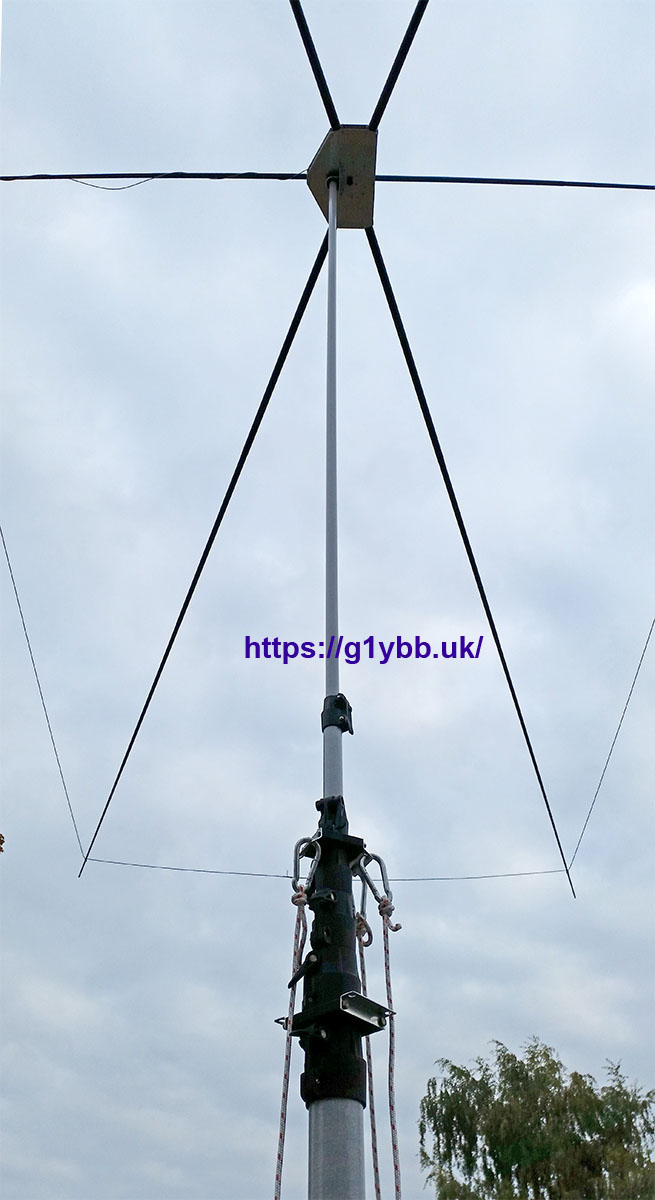
Pushing it up to about 30 feet to test I trimmed 10mm off each end to arrive at the below plot. Almost perfect match with the simulation.
Time to test it on the air. Hmm. SWR with real RF way up in the red. It couldn’t be but was. I wondered if the choke wasn’t just not working but was working against me? It was meant to be 17 turns of RG58 so I hoped tightly packed RG316 would have same effect. I tried a GM3SEK choke my end in the shack, no good. Hmm. Talking with a couple of friends one suggested taking the N type off the plate.
I couldn’t think this would have any affect but it was worth a try before I started cutting things.

Well snag my blade! All was good now. The metal plate attached effectively to the braid of the coax certainly had some negative effect!
So now I had a working 20m moxon beam.
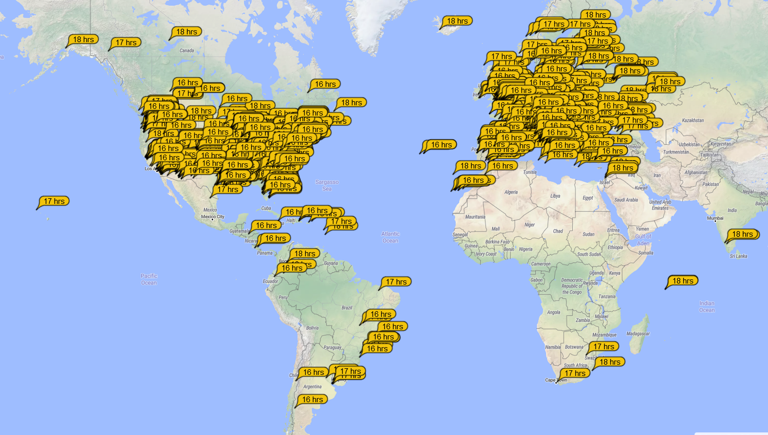
As it turned out come CQ WW SSB weekend it was too windy for me to use the moxon, but I have had great success working USA on FT8 since. The below is where I was heard for a few hours with the moxon aimed for USA and working mostly USA and Canada.
Final weight of the finished moxon was 3.2kg and it does compact down small enough to go on a roof rack, possibly even inside my estate though it could be a squeeze. I aimed for the SSB section of the band but it would have probably been to aim lower in the band to get a more usable SWR at the CW end. But performance wise I’m very happy with the new moxon.
Edit: October 2021
Since the initial build I have since soldered a little wire to the end of all 4 wire ends to move the resonance down to the digital end of the band. And since that I have made a 3 section wind up aluminium mast and can now use a rotator instead of running downstairs and up the step ladder!
But more interestingly, I re-measured the moxon at about 12.3m above ground on the new mast with LBC400 coax so very low loss at 14MHz and the whole band is below 1:1.6. (I really must set the date on the analyser!)