Building the W8NX Short Trap Dipole
Building the W8NX Short Trap Dipole
For the past five years, I have been operating the lower bands (30, 40 and 80 meters) with a trap dipole that was modeled after a web article written by John DeGood NU3E. [1] While the antenna performed well, a monsoon storm last summer beat it up enough that the antenna wire broke at the center balun.
So I climbed the tower and lowered the remains of the antenna to the ground for repairs. On closer examination, I discovered that the relentless Arizona sun had taken its toll on the traps. The insulation on the exposed ends of the coax had rotted away. They were still working, but would need to be rebuilt and weatherized to insure good operation many years into the future.
Since I was going to have to rebuild the antenna, I started thinking about whether this antenna met my current needs and wishes. I had been wanting to get on 160 meters at this QTH for some time, but my small back yard would not accommodate an antenna of that size with conventional coaxial traps.
Some research led me to a QST article for a short 40, 80 and 160 meter trap dipole. [2][3] This design used double-wound traps made from only the inner conductor of RG-58 coax. The trap design was a little more complicated, but would almost fit into my back yard. I decided to pursue construction of this antenna, and bend the 160 meter end wire, if necessary to fit into the yard. A tradeoff of the loss of 30 meters for the addition of 160 meters fit my operating needs well.
In the construction of my prior trap dipole, I had used my MFJ-259B antenna analyzer to measure and adjust the traps and wire lengths. Since that time, I have acquired one of the new, cheap NanoVNA vector network analyzers[4][5]. It looked like the nanovna might make the job a little easier and present a clearer picture of the antenna characteristics. So I set off to construct my version of the W8NX short trapped dipole. Follow along for details and tips on how you might build this unique classic trap dipole for the lower bands.

Material List (not including miscellaneous mounting hardware specific to each installation):
Dimensions include reasonable waste after cutting
RG-58A/U coaxial cable – 100′ (https://thewireman.com/)
2″ Schedule 40 PVC Pipe – 2′ (local home improvement store)
3″ Schedule 40 PVC Pipe – 2′ (local home improvement store)
18 AWG Copper Clad Steel Antenna Wire – 150′ (https://thewireman.com/)
(Note * You may substitute nearly any wire for this. But the copper clad steel wire will last decades)
Wire Clamps or Crimps (your choice) – 16 (local home improvement store)
1:1 Center Balun – 1 (https://www.dxengineering.com/)
Carpet Tape (double-sided tape) (local home improvement store).
Preparing the coax
The center conductor of the coax is used to wind the traps. Note the A/U designation that is specified. This has the solid polyethylene (PE) dielectric. This is the hard (but not brittle) translucent insulation, not the white foam type found on other types of RG-58 cable. This particular rg-58 has a high breakdown voltage to allow for a full kilowatt capability when the trap is wound as directed, according to the original article. Other types of RG-58 such as that intended for computer networks will not work at those power levels.

Strip the black outer jacket off of the coax. Everyone probably has their own idea of how to strip a long length of cable. Use appropriate caution. Here is how I do it…
For the first 40 meter trap, I cut an 18.5 foot length of the coax and clamped one end in my bench vice to hold it while I pulled on the rest of the cable. Using my sharp pocket knife (a razor knife would work, too), I carefully held it at a very shallow angle to the cable. Keeping the cable tight, I held the knife stationary and backed my whole body away from the the clamped end of the cable. This shaved off a strip of jacket about 1/4″ wide.
I was very careful to make certain that I did not pull the knife toward me. I held the knife stationary, and backed my whole body away from the the clamped end of the cable, keeping the cable tight. When I slipped off, I just started again. That resulted in a cable with the jacket removed, and the braided shield exposed.
To remove the braided shield, do not try to pull it off. Start at one end and push it down toward the middle of the cable. This will cause it to loosen, and as you work your way to the other end, you can easily work it off the center conductor and its insulation. Save the braid, it’s nice for bonding/grounding things…

When this is complete, repeat the procedure for a second 18.5′ length for the second 40 meter trap, and two 30′ lengths for the 80 meter traps.

Preparing the trap forms
Note that the 2″ and 3″ nominal dimensions of PVC pipe refers to the inside diameter of the Schedule 40 pipe. The outside diameter will be larger, but that is how it is specified in the stores. I will be using the nominal 2″ and 3″ designations for the rest of this article. This stuff is cheap. The local home improvement store had some 2′ lengths that were convenient, and plenty long enough for the job.
Cut two lengths of 2″ PVC pipe to 3.25″. Sand the cut edges to remove any burrs or sharp edges. These are the 40 meter trap forms.
Cut two lengths of 3″ PVC pipe to 3.5″. Sand them to remove burrs. These are the 80 meter trap forms.

For marking the position of the various holes to be drilled, I have created a paper template that may be printed out, cut to size and taped onto each trap form. The precise location of each hole to be drilled is marked on the template, but it is not too critical. Just get it close. The template is available as (W8NX_Trap_Layout.pdf).

Final Trap Dimensions:
40-Meter Trap
2″ ID (2-3/8″ OD) Schedule 40 PVC Pipe
12.3 Turns inner winding
10.7 Turns outer winding
Pipe Length = 3.25″
80-Meter Trap
3″ ID (3-1/2″ OD) Schedule 40 PVC Pipe
14.3 turns inner winding
12.9 turns outer winding
Pipe Length = 3.5″
Using the template
Print the PDF template using 100% scaling on your printer.
Taping this template centered on the trap form, use a 5/32″ bit (not critical, just make sure the antenna wire fits through) to drill out the Ant-1, Ant-2, Ant-3 and Ant-4 holes. These will be for mounting the antenna lead-in pigtails across the diameter of the 40-Meter form.
With the same drill bit, drill out holes 1, 2 and 3. Mark hole 4 on the form but do not drill it yet, as its final position will be set later.
Remove the template, and mark each hole with its identification, so you can tell where each one is without the template.
Chamfer the holes with a 1/4″ drill bit, twisted in your hand to remove sharp edges. Don’t use a drill for this, as it will catch in the hole and instantly make it bigger. Don’t ask how I know…

Trap Winding:
Cut a strip of carpet tape about 1-1/2″ wide, and long enough to wrap around the circumference of the 40 meter trap (about 4″). Stick the carpet tape to the coil form, centering it on the form.
Insert one end of your 18′ long piece of center conductor into hole #1, from the outside. Leave about 6″ sticking through to the inside. On the outside, wind 12.3 turns over the carpet tape and feed the wire back to the inside of the coil form through hole #2.

Continuing with this long end of the wire, bend it back towards the starting hole, and pass the wire back out of the coil form through hole #3.

Wrap 10.7 turns onto the outside of the existing coil, in the same direction as the first winding. Do not pass it back to the inside, yet. Temporarily tape it in place to hold all of the windings securely.

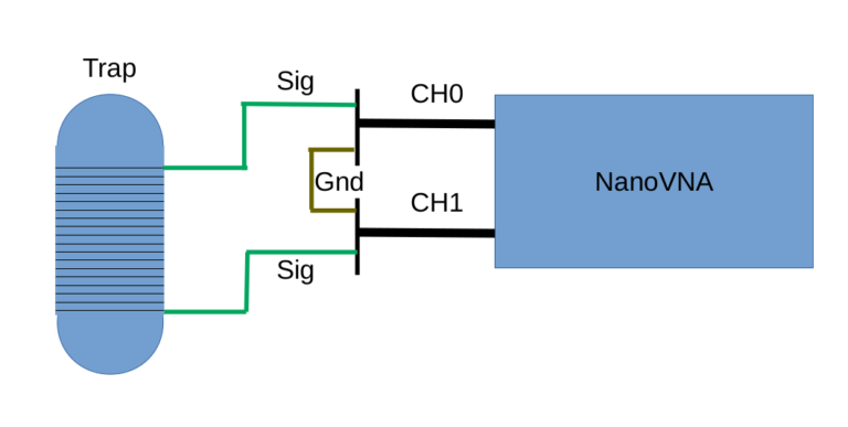
Strip the end of the wires, and measure the resonant frequency, using the NanoVNA [6].
To do this, find a way to split each of the two sma connectors into a shield (gnd) and signal wires. You can take an SMA jumper and cut one end off, connecting alligator clips to the shield and center conductors. Or you can use a variety of adapters to achieve the same function. I used an SMA to BNC male adapter, followed by a BNC female to banana jack adapter, followed by alligator clip test leads.
Once the leads are split out, connect the two shields from CH0 and CH1 together. Then the CH0 center conductor goes to one side of the trap, and the CH1 center conductor goes to the other side of the trap.
Set up your NanoVNA trace to the logmag setting. This will measure the loss through the trap. Then set the center frequency to the sweet spot you are shooting for (what frequency you want your antenna resonant at), and the span to about 8 MHz.
The NanoVNA should show something like a strong dip near your target frequency.
Mine came out a bit low in frequency, about 6.8 MHz (with the specified 11.3 turns from the original article).
If yours is low in frequency, unwrap an inch or two of the outside winding, and re-measure the resonant point, pulling the last bit of wire out away from the other windings, so that it’s not adding as much to the inductance of the trap. After a few tries, I walked the resonant frequency up to about 7.150 MHz. That was with about 10.7 turns on the outer layer.
If your frequency is high, lay more of the outer winding to make it longer by an inch or two. By adding or subtracting wire, you should be able to walk the frequency to your personal sweet spot.

Mark the form at the point where the wire pulls away from the form, and drill another hole there to pass the wire back to the inside of the trap.
Cut the wire end off so that you leave a few inches.

Make a final measurement with the wire at that length. Mine didn’t really change.
Tape the outer coil in place tightly. From my experience with my first trap dipole, I can say that electrical tape holds up well n the Arizona sun. It was still weatherproof after 5 years exposure.

For the 80-meter trap, the inner winding is the specified 14.3 turns. The outer winding ended up being about 12.9 turns for my selected frequency of 3.750 MHz.
Constructing the antenna pigtails
The antenna pigtails are simply pieces of wire on the ends of the trap that are securely fastened to the form and provide a connection point for the antenna wires. They are designed to relieve stress on the trap windings when blowing around in the wind.
Cut a length of antenna wire about 16.5″. Place the wire through antenna holes ANT-1 and ANT-3 on the end of the form. Bend the wires toward the center, and wrap one end tightly around the other. Then, solder it in place. Repeat for other side of the form from ANT-2 to ANT-4.
The wire ends of the trap windings are somewhat stiff, and prone to break if flexed back and forth enough times. To prevent this, use a piece of the leftover braid from the rg58 coax to connect the wires of the trap to the antenna pigtails. It is very flexible, and should significantly reduce the stress on the connection.
I used a couple of cut off crimp connections from some ring terminals, placing the braid and the trap wire into a crimp connection and crimping them together. Then I soldered them for good measure.

Wrap the other end of the braid lead around the center of the antenna wire lead, inside the form. Leave enough slack so that movement (rotation) of the antenna wire does not stress the end of the coil wire.

Once the final testing is complete, and the traps are tuned to their sweet spots, you can weatherproof the traps by using liquid tape on the exposed trap wire inside the form.

Antenna Supports
Your end supports should be in place before you start installing and adjusting the antenna. Of course, each installation will be different.
My trap dipole is installed in an inverted vee configuration, as it was too long for my backyard, even though it is a shortened version. 160 meters takes a bit of space! Hanging from 45′ in the center, it comes down to about 10′ to 15′ on the sides.
One side is still too long for my yard, so I made a PVC sleeve for it to droop inside vertically, then horizontally for a few feet to take up the extra length.

That keeps anyone from touching the actual wires and burning themselves while I am transmitting. It’s not optimal, but it gets me on the air on the low band.
I decided to attach the vertical PVC support to a small shed in my yard. However, I wanted the horizontal extension to be as high as practical. So I made a bend in the configuration to get the horizontal pipe a little higher on my back wall.

The other leg of the antenna fits in my backyard without letting it droop down. It is a few feet above my roof at its lowest point. Then a rope attaches the end to another PVC pipe up about 10 feet.
A balun is appropriate for any kind of coax to dipole connection.

First, add the 40 meter wire segments to the balun. Loop the 40M wire through the eyelets on top, one wire to each side, of course. Twist the end back on itself and solder. These form strain reliefs for the antenna connections. Then use some of the leftover braid and ring terminals to connect the terminals on the side of the balun to the antenna, below the strain relief. Keep the braid loosely hanging, so it is not taking any of the weight of the antenna.
Connect the coax that comes from your shack to the bottom of the balun, and hang the balun as high as you can get it. Mine is about 45′ high on my tower. If you have a tower, it will be good to make a mount to keep the balun a few feet away from the metal tower. I clamped a pipe sticking horizontally away from the tower for mine.

Start with about 33′ of wire on each side. Put an insulator at the far end, and hoist the balun into the air (preferably at it’s final height). Then use a rope on each insulator to hoist the end up to it’s expected height above ground.
With my balun at 45′, on a ladder I could reach the ends of the 40 meter wires as they hung loosely down the tower. This allowed me to trim the ends, and then pull them out away from the tower. So I only had to hoist the center up once.
Plot the SWR curve on the NanoVNA[7], and trim the wire a bit at a time until you see a dip at your intended frequency. It should start out low in frequency, and rise in frequency as you trim pieces off the end. Trim it equally on each side. Mine ended up at about 32.5′ on each side.
Once the 40 meter segments are cut to length, replace the insulator on the wire ends with the 40 meter traps. This is important! Make sure that the original ends of the 40 meter segments reach all the way to the trap form, where the braid in the trap attaches to the pigtail that you attached earlier. Otherwise you will be inadvertently lengthening the 40 meter segment, and the resonant point will no longer be where you intended.
Attach the traps to the antenna wire with crimp lugs and solder. On the far end of the trap, attach the 80 meter antenna wire extensions. Follow the same procedure as above to trim the 80 meter segments to length. Start with about 12 feet, and trim down from there to get an SWR dip at your intended 80 meter sweet spot. Mine ended up at 11′.
Repeat the steps above to add the 160 meter trap and extension wires. I started with 19′, and trimmed down from there, ending up at 15.9′. I don’t know how the drooping and bending of the ends of the 160 meter segment affect the SWR or performance, so it’s best to measure and trim your own antenna.
After all three bands were adjusted where I wanted them, I used the nanovna-saver [8] Windows program to get a clean plot of each band.
40 Meters SWR

The 40 Meter plot shows a nice dip at 7.150 MHz, and the entire band is under 2.5:1 SWR. This is easily handled by my LDG AT-100Pro automatic antenna tuner. I suspect that a radio’s internal tuner would handle this as well.
80 Meters SWR

The 80 Meter plot shows a nice dip at 3.750Mhz. My auto tuner handles the entire band without complaining, as does my manual tuner.
160 Meters SWR

160 Meters shows a nice dip around 1.900 MHz. My small auto tuner will tune about +/- 25khz from the center on this band. The manual MFJ tuner will tune to under 1.5:1 SWR across the entire band, but it is really sharp tuning.
Future Plans:
I intend to add a linear amplifier to my shack in the future. At that point, my small LDG tuner will no longer be appropriate, and I will replace it with an auto-tuner that can handle higher power. At the same time, I will choose one that has a wider range that it will tune the entire 80 meter band (and maybe 160, as well) without problems.
In the meantime, I will use this trap dipole to get on the lower bands, using my manual antenna tuner as necessary to get on the frequency I desire.
Notes:
1.) John DeGood, NU3E
An Attic Coaxial-Trap Dipole for 10, 15, 20, 30, 40 and 80 Meters
http://degood.org/coaxtrap/
2.) A.C. Buxton W8NX
Build a Space Efficient Dipole Antenna for 40, 80 and 160 Meters
July 1992 QST, pp. 35-36
3.) Russ Healy, NJ2L, Senior Assistant Technical Editor
Trap Construction Information for Al(W8NX) Buxton’s July 1992 Dipole
September 1992 QST, pp. 88
4.) Phil Salas, AD5X
Review – NanoVNA Vector Network Analyzer
May 2020 QST, pp 39-43
5.) IMSAI Guy
#480 NanoVNA Made Simple
https://www.youtube.com/watch?v=QJYeFpiqY8c
6.) W2AEW
#315: How to use the NanoVNA to measure a low-pass filter
https://www.youtube.com/watch?v=F17mN5uuzGY
7.) W2AEW
#314: How to Use the NanoVNA to sweep / measure an antenna system’s SWR and optimize its tuning
https://www.youtube.com/watch?v=xa6dqx9udc
8.) nano-vna_saver.exe
Rune B. Broberg, NanoVNA-Saver Authors
https://github.com/NanoVNA-Saver/nanovna-saver


Comments
Post a Comment