Preamp using the ATF54142 FET
This design was made in 2006. It came back to my attention as my friend Jack PE1KXH asked for another PCB board.
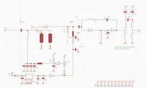
The design uses source feedback and has a diplexer on the output. The diplexer takes care of the output of the fet and assures that it is always correctly loaded. The input circuit is rather wide, the input impedance of the fet is close to 50 Ohm, thus requiring not much matching. To compensate for this lack of filtering in the input, the preamp is equipped with a very narrow filter in the output.
The design performs rather well, with a noise figure of 0.3dB it is good enough for EME and that was why I designed it. It uses mostly SMD components, my eyesight must have been better in 2006.
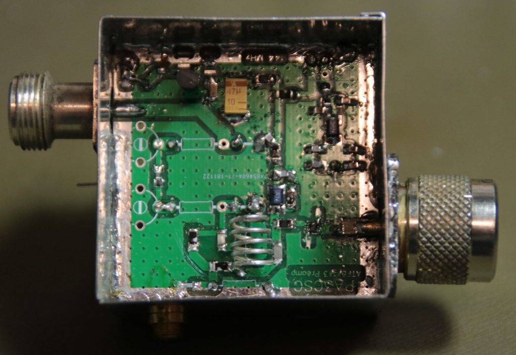
The preamp fits in a tinned box 55 x 55 x 50 mm
The coupling capacitor in the filter can be made by twisting some 2 pieces of wire together.
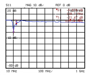
Some measurements:
First the input match of the preamp ( S11 )
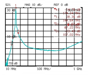
The gain of the preamp (S21 )
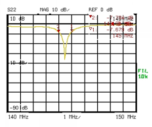
The matching on the output port ( S22 )
Jack PE1KXH build a new preamp. See the pictures below.
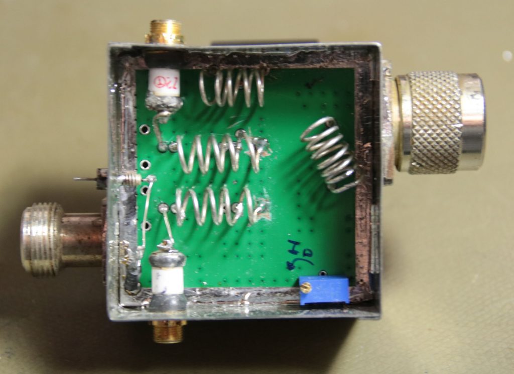
Inductors
The inductors can be place on the bottom of the board:
Input inductor 7 wdg 1mm cuag 6mm dia
bandpassfilter 5 wdg 6mm dia 1mm cuag Tap 1wdg from cold end
diplexercoil mount on bottom side (no space on top side) 5 wdg 6mm dia 1mm cuag