|
SITE
MENU |
How to
Use an Antenna Tuner
Yes, "TRICK" YOUR
RIG! In the block diagram below we have typical Hf station setup consisting of, from lert to right,: An HF Transceiver A Linear or power amp Low Pass Filter Swr/Watt Meter combo The Antenna Tuner A Dummy Load The MOST IMPORTANT PART......THE ANTENNA!
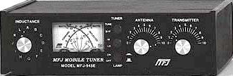
PLEASE DISREGARD THE LINEAR AND LOW PASS FILTER FOR THE MOMENT! (Your station may not use them) You will notice that.... first, from left to right, you have the transceiver, Swr/watt meter, ANTENNA TUNER and then the antenna on the output. The rf moves from the transceiver to the SWR/WATT meter, then finally thru the "tuner" and out to the antenna. You just learned how to hook it all up! Just remember that our goal is to make the transceiver think all is well, and in order to "read" the SWR and Power out pertaining to "all is well"......at the radio's output....the swr meter must be between the radio and the tuner. NOT ON THE ANTENNA SIDE! Now Let's learn how to "tune" that "tuner" Most antenna tuners have an inductance rotary switch and two capacitors. (refer to photo at top of page) The capacitors are often labeled ANTENNA and TRANSMITTER. In some antenna tuners the inductance switch is replaced with a continuously variable inductance, popularly known as a roller inductor. Let's assume you're using a tuner with an inductance switch, because they are the most common. SHOCK HAZARD! NEVER TRANSMIT WITH THE TUNER COVER OFF AS IN THE NEXT STEP! TURN OFF THE POWER TO THE RADIO! Place both capacitor controls at their mid-range positions. Don't trust the knob markers if this is your first experience with the tuner! If you are comfortable with the next procedure, remove the cover of the tuner and turn the knobs until the moving capacitor plates are only half meshed with the stationary plates. If the knobs are pointing to half scale with the reference markings on the knobs and front cover, consider yourself lucky. If not, loosen their Allen screws and rotate the knobs so that they point to mid scale. Re-tighten the knobs, replace the tuner cover and you're ready to go. Turn the radio on and tune receiver to an un-used frequency on the band you desire, listen for a few seconds, with the antenna and transmitter controls at mid scale, move the inductance switch to each of it's positions until you hear the loudest noise or signals coming into your radio. Then, rotate the antenna and transmitter controls until you get to the absolutely loudest noise or signal level on the radio. All three of these controls interact with each other so practice on several bands to get the "feel" of the procedure. Select your final band of operation and repeat the procedure above. When noise peaks out using your ears and the S meter, your tuner settings should be very close for final operation.With your rig set to low power monitor the frequency to assure that it is not in use, send your ID then transmit a continuous carrier while you tweak the antenna and transmitter controls for the lowest reflected power reading with the highest output power as read on the Swr/Watt meter. You may find that you have to vary the position of the inductance switch a position or two either way to get your best match. Play it safe and un-key before turning the inductor switch...un-key first....turn the switch...key up....repeat as needed until lowest SWR and maximum output. Be gentle to your radio; keep the key-down periods as short as possible. Depending on the impedance at the antenna input (and the overall design of the tuner) you may not be able to obtain a flat 1:1 SWR on all frequencies and bands. Also important to remember is that your Swr will change, go up, as you tune further away from the frequency you used to "trick" your radio! So re-check and re-tune as needed as you move around the band. You can get an idea of your SWR bandwidth by starting with your original frequency, and using the procedures above withlow power, (don't move any knobs or switches after best setting)....sweep or tune your VFO up and down the band while watching the SWR readings and note the frequency where the SWR reaches 2:1 at the higest and lowest frequency. Stop there! Example: If your on 40 meters at say...7.262mhz as your starting point, and your SWR is 2:1 at 7.292mhz and the highest swr going the other way is 2:1 at 7.259mhz, then your "safe tuning range" without retuning the antenna tuner would be about 60khz. Keep in mind to use very low power and ID because your signal may be heard for a split second as you tune across the band! When that transmit key is down, someone somewhere can hear you. Even a dummy load gets out somewhere! Remember your "TRICKING" your way around a good antenna! ++++++++++++++++++ So what kind of tuner should I buy? Click on the ad below to see the latest ARRL Book "A Guide to Antenna Tuners" Loaded with information for choosing the right tuner for your ham radio station!
Editors note: In reality, there is no "tricking" involved anywhere and we were playing with words here like "tricking, fooling", etc. It is useful to employ a matching device, the antenna tuner, between the transmitter and the antenna feeder when antennas with complex impedances are used..... so the transmitter will "see" a 50 -52 ohm load even though a significant mismatch is present at the antenna feed point. The tuner, matchbox or transmatch as it is sometimes called, will not correct the actual SWR condition on the feed line OR antenna, but it will resonate the antenna system as a whole that the radio "sees" on it's output and allows the transmitter to deliver as much power to the antenna system as possible within the design parameters of the tuner. The transmitter now can produce it's rated power out to the tuner in the hopes that the tuner can do it's job and get most of that power into the antenna system with some efficiency. Bottom line: Your transmitter will not know that you are trying to "load up" those old rusty bed springs or that poor excuse for an antenna! Just because you're now seeing that "magic" 1 to 1 VSWR reading on the meter does not mean you have changed the design of those old rusty bed springs or whatever you're trying to us as an antenna!!! The more efficient your antenna system.....the better! 73
POWERED BY HAM RADIO! |