FILTERS
There have been a number of inquiries regarding transmitting and
receiving filters for eliminating 6m interference. I have been
quite actively trying to combat such problems here, and will share a
few of the things I have used successfully to prevent interference
at my own home.
LOW PASS FILTERS
Industrial Communication
Engineers, LTD. (TEL: 800 423-2666 or 317 545-5412,
P.O. Box 18495, Indianapolis, IN 46218 USA) has low
pass transmitting filters with a cutoff frequency of 54 MHz.
The models (and peak power handling capability) are #425 (300
watts), #426 (1500 w) and #427 (6 kw). Their model #427
claims 80 db attenuation above 56 MHz. You can get any kind
of connectors on them you want, although you will probably have to
provide them if you want other than N or UHF. At my
installation, I use a #425 on the input of my amplifier, and a
#427 on the output of the 8877 amplifier. As of 2013, I am
not sure they are still in businss. More information
Additional information on low pass filters for use on 6m can be
found on the N6CA 50
MHz web page.
K1WHS QRO 50 MHZ LOW
PASS FILTER
Design and performance of a QRO low pass
filter for 50 MHz is shown HERE.
Using the same design, a larger version was built by W7GJ, as
outlined below:
This very heavy duty 50 MHz Low Pass Filter
was constructed by using a pair of 50 pF, 15 kVDC ceramic
doorknob capacitors, and three air wound self supporting
coils.
The center coil ( L2 ) is 6 turns, 2.5" long, using #6
AWG copper wire wound on a 7/8" diamter form. Input
and Output coils ( L1 and L3 ) are each 4 turns, 2'' long,
using #6 AWG copper wire wound on a 3/4"
diameter form. The enclosure was built to fit the
space required for the coils. The box is 12"
long, 4" wide and 4.5" high. Baffles were
mounted around each capacitor to prevent enclosure
resonance at UHF harmonics. 7/16 DIN connectors were
used on both ends.
Insertion loss was measured at less than .06 dB, with
attenuation greater than 24 dB at 100 MHz |
|
YU7EF LOW PASS FILTERS
ZL1RS and YU7EF constructed a version of
the above K1WHS
50 MHz Low Pass Filter but used smaller
capacitors and metric wire sizes. The results are
shown here.
|


|
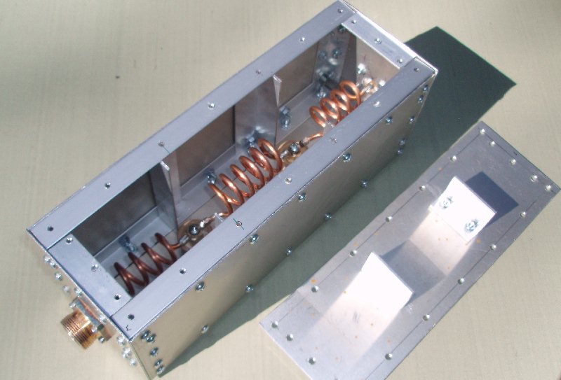
YU7EF also
built a 7 pole 50 MHz low pass filter, using the smaller
7.5 kv doorknob capacitors. A photo of the filter
constructed by ZL1RS is shown to the right.
Construction details and performance information on a
QRO version of this filter is available HERE.
 |
 |
YU7EF also
offered a design of a similar 7 pole low pass filter for
144 MHz:
 |
|
STUBS
I also constructed a filter on the back of my 2m amp, which
combines two OPEN quarter wavelength sections - one for "shorting
out" the even harmonics and one for the odd. It is capable
of handling lots of power and I don't ever have to worry about
blowing up THIS filter! Sorry I don't have a scanner handy
so I could provide drawings, but I will describe the
construction. I used a 4' long piece of 1" square (outside
dimension) aluminum tubing with 1/8" thick walls. Off center
(see center conductor lengths below to determine appropriate
connector location), I mounted a pair of N connectors on opposite
sides of the tubing, and drilled an access hole on a third side so
I could solder a little jumper of tubing (with a small hole in the
middle of it) to connect across between the two N
connectors. Through the hole in the middle of the little
jumper, I ran small copper tubing orthagonally, so it extended
both up and down through the square aluminum tubing. The
center conductor I used for this was 3/32" diameter copper, but I
think large stiff copper ground wire also would work well. I was
not concerned with the impedance of the quarter wave stub
sections, since they will look like a short at the harmonic
frequency regardless of exact impedance. For the 150.450 MHz
stub, the section should be 19.34" long, and for the 100.3 MHz
stub, it should be 29" long. The longer piece was supported
twice with little 1/4" thick spacer dics (3/4" diameter teflon rod
with 1/8" holes drilled in the center) and the shorter piece just
had one such spacer. No fancy test equipment available here
to provide figures on db attenuation at the harmonic frequencies,
but I did notice my second harmonic (which was already quite weak
on my stereo receiver) get even weaker. The SWR was around
1.7:1 at 50.125 MHz, which didn't seem to cause any problems for
my 8877 amplifier. I attach it to the amp (which is sitting
on top of a book shelf so the rear of it is flush to the rear of
the shelf) so the long end of the aluminum tube points down and
the short end rises up behind the amp. Maybe someday there
will be photos/drawings on my web page, but in the meantime, I
wanted to share this info with anyone who can use it to help get
(or stay) on the Magic Band.
Additional information on well-matched and effective VHF/UHF open
stub filters was prepared by G4SWX.
The
basic idea behind John's Coaxial Stub Filters is to keep the
impedance (at the pass frequency) of the elements at the output
port of the filter the same as at the input - hence you can match
the whole filter by transforming the input impedance to its
conjugate at the output. The simplest filter of this type uses a
quarter wave open circuit @2f on the input and open circuit
quarter waves @3f and 4f on the output. This is a 'magic'
combination because @f the impedance of the 2f stub is the same as
the parallel combination of the 3f and 4f stubs. All that is
needed is to transform the impedance at one end into its conjugate
at the other.
John suggests that the easiest way to do this at high power is to
use a coax line rather than an inductor to do this transformation.
To construct a high power filter using the above coaxial elements,
John recommends a quarter wave open circuit @100MHz on the
input and quarter waves open circuit @150MHz and 200MHz on the
output. Join the input and output sections of the filter together
with a low loss coaxial line (0.265 x velocity factor) wavelengths
long. This will give you >20dB return loss ( <1.2:1
vswr) at the pass frequency. Shorted half wave stubs don't really
help a lot and they tend to up the insertion loss ! A simple rule
is that the more junk that you put into a filter the higher the
insertion loss !
Although it takes a little bit of room to construct one of the
above G4SWX filters on 6m, the coax could be coiled up, so the
space required is minimal. Or, if you really want a high
power and low loss version, you could construct the entire thing
using square aluminum tubing welded together. If you are
using rigid line sections with a single teflon spacer in the
center, the lengths should be determined using a velocity factor
of .985. Remember to make the section between the "input" (a
single quarter wave open stub at 100 MHz) and the "output" (the
pair of open quarter wavelength long stubs for 150 MHz and 200
MHz) from a 50 ohm section. To make an air line for 50 ohms,
the inner conductor and square aluminum tubing should be sized as
shown below:
2.17 = (the inner square tubing dimension)/(inner conductor
overall diameter)
50 MHZ STUB FILTERS
Please
see the FILTERS section of the Harris
Platinum I amplifier page for two different types of stub
filters for 6m.
TVI RECEIVING FILTERS
I have an outdoor TV antenna situated very close to my
transmitting antennas. When the coaxial lead from this comes into
the house, I have a Radio Shack distribution amplifier to send the
TV and FM signals to the appropriate receivers in the house.
The gain on this amplifier had to be turned entirely down to
prevent overloading. In addition, I had to install the
following filters immediately ahead of the amplifier (toward the
TV antenna):
1. First, I installed several Radio Shack ferrite split
ring toroid filters on the RG59 coaxial cable from the TV
antenna. This is to remove any "common mode" RF that is
traveling on the shield of the cable.
2. Following that, I installed coaxial "T" connectors, with
open quarter wavelength stubs tuned to 144.100 MHz and 50.125 MHz,
to try to "trap out" any overloading signals.
3. Following that, I installed a 50 MHz notch filter
(manufactured and distributed by K1UHF).
This is a commercial quality filter with F connectors that has
very high attenuation for signals in the 6m ham band, and is very
effective.
4. Following that (just in front of the Radio Shack
distribution amplifier), I installed an Ameco high pass filter
(cutting off below 54 MHz) with F connectors. This was
obtained from Ham Radio Outlet. This filter was grounded to
a large ground wire heading directly out through the wall to an 8'
ground rod.
The above filters effectively prevent unwanted frequencies from
overloading the distribution amplifier. However, it was also
necessary to protect the non-ham equipment (VCR, TV, telephone
answering machine, and stereo amplifier/tuner) from "common mode"
RF interference (RF signals that simply are passed into the
equipment on the shield of the coaxial cable, or induced on the
cords leading from the equipment). This was done by
installing the Radio Shack split ring ferrite filters mounted as
close to the equipment as physically possible, on all the speaker,
power cords, and antenna leads. This combination of filters
seems to very effectively permit me to receive TV and FM signals
while transmitting on all bands.
Additional information regarding TVI/RFI can be found at Amateur Radio TVI RFI Solutions
.

©W7GJ 2014, Page revised 18 April, 2014
