Caged Fan Dipole Project
There are a large number of antenna designs for HF. One choice out of many is the fan dipole. The ability to transmit of multiple bands without needing a tuner (and even more with a tuner) is a very desirable factor in choosing a versitle antenna for HF.

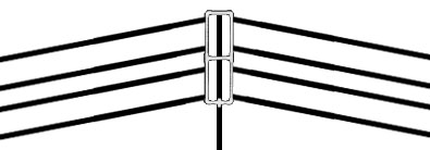
Before this particular caged fan was ever even concieved of, there was the WA5VRQ “Billy Ray Bubba” fan dipole for 40 and 75 meters. The WB5SPA club has often turned to “Billy Ray Bubba” on field day. (left image)
Even at about 20 feet off the ground this antenna works reasonably well. Raising to the 35 foot level made a considerable difference with both transmit and receive. Inspiration struck when WD5DJX upgraded his two leg horse fence antenna to a 4 leg one. I noticed an immediate jump with his signal on 75 meters. This 4 leg antenna heard better, transmitted better, and was more broadbanded. All of this from adding an addition run of the horse fence material on each side seperated by about a foot. What we do know is that the wider the antenna elements are the larger the bandwidth. It is also not necessary for those elements to be completely solid for this to work. This is the magic of the horse fence antenna. The ribbons used for the antenna elements have several seperate stainless steel wires running through the length. All the additional metal makes for more capture on recieve.
 One late night brainstorming session later an idea was born. Just click on the diagram for a full size complete diagram roughly to scale. My thought was adding this concept to the fan dipole that had served me so well. In these center fed antennas most of the radiation comes from the center area. The elements on the “Billy Ray Bubba” had very little separation for the entire middle part of the antenna. I figured it would make more sense for the spacing to be consistent throughout the entire run of the elements. All of the elements were carefully hooked to the feed point with exactly the same length of wire. I decided to solder those together connected to a 1:1 current balun, and fed with rg8x coax.
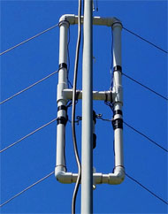
 The most important part of the antenna is where all of the elements connect to the feed point. The rest is easy. I constructed a frame out of pvc pipe to hold the elements in place. I decided that I’d go with a two foot seperation on 75 meter and 8 inches for the 40 meter runs. As close as the elements were in the first fan dipole especially near the feed point I didn’t figure that this spacing would present any problems. The 40 meter elements are inside of the 75 meter elements. I was careful to make sure that the spacing of the elements were equal from the center point between the elements.

Image on the right is a close up of the center feed point of the antenna. Image to the left is the original image from the October post. Once the center point was done all that was left was to use 4 two foot long pvc pipes as spacers and to tension the antenna. Anchoring it to the end points at the top and the bottom kind of volley ball net style kept the spacing consistent and has proven durable though wind, hail, ice, and combonations thereof. My lengths are 59 feet on 75 meters and 31 feet on 40 meters. The actual real world deployment had the angle of the inverted V close to 60 degrees. The virtual width of the combined element shortens the length slightly. Other factors that will effect length are angle of the elements, material of the wire, and whether or not it is insulated. Since every QTH is different it is a good idea to cut the antenna long because its always easier to make it shorter. On the spacers I ran the wire though small holes drilled in the right spots with the wire wrapped in a slip knot kind of method that makes it very easy to shorten and lengthen the elements for tuning, The excess wire is wrapped around the pvc pipe and taped in place.
This same concept can be applied to any combonation of bands depending on how much space you have to work with. The 40/75 is just the example of the prototype.
It covers with less than 2:1 SWR without a tuner 3750khz to 4050khz, 7100khz to 7400khz, a good slice at the top of 15 meter that with tuning could cover the entire band, and also 27.5mhz to 29mhz. The entire technician phone portion of 10 meters has virtually no swr at all. After I take the SWR analyzer to this again I can post a more detailed report. With the tuners I’ve worked 75, 60, 40, 30, 20, 17, 15, 12, 10, 6, and even 160 but with a labor intensive tune with poor peformance. This has gotten excellent signal reports on 100 watts on every one of those bands except 160. I’ve even been accused of running power on 75. I’ve been told that I have one of the loudest 100 watts stations on the band. Whether or not this is true I cannot say, just going by what I’ve been told. I have listened on remotehams.com remotes to my signal and it does seem to be an order of magnitude better than it was.

More pictures and details to come… Check back! There are still links to add and construction details. This page is far from done. I hope its a good enough start.


