|
Tune
Around!
SEARCH
CQ-Calling All
Hams!
About Hamuniverse
Antenna Design
Antenna Safety!
Ask Elmer
About Batteries
Code Practice
Computer Help
Electronics
FCC
Information
Ham Hints
Humor
Ham Radio News!
Post Reviews
Product Reviews
Ham Radio Videos!
HF & Shortwave
License Study
Links
Midi Music
Reading Room
Repeater Basics
Repeater
Builders
RFI Tips and
Tricks
Ham Satellites
Shortwave Listening
SSTV
Support The Site
STORE
Vhf and Up
Contact
Site Map
Privacy Policy
Legal Stuff
Advertising
Info
|
The 2 Meter 146mhz Slim Jim Antenna
Using Aluminum Tubing!
By N4UJW
Hamuniverse.com
Further Experimentation With The 2
Meter (146mhz) Slim Jim Antenna Using Aluminum Tubing!
By N4UJW
Hamuniverse.com
Well, here I go again! Not wanting to be out done
by myself and after having the temporary J Pole To Slim Jim Conversion
project lay down on the ground due to some high winds we had, I decided to
get with it on this 81 degree day in January, 2006 (yes, 81 degrees in
Texas in January! Won't last long!)... and rebuild the old Slim Jim Antenna
Conversion with aluminum tubing using half inch diameter "junk" tubing
that I found hiding from me.
THE PARTS LIST
The following
instructions may help you if you decide to try the Slim Jim antenna with
aluminum tubing. Refer to the Slim Jim Antenna Project for more details if
needed.
I used half inch OD "junk" aluminum tubing cut to these final
lengths:
NOTE: THE TOTAL LENGTH FROM TOP TO BOTTOM IS 57 1/2 INCHES.
You should end up with with a very, very elongated rectangle with a
space (air gap) between the shortest section and the one above it of about
1 inch. (Again.....see pictures and refer to the original Slim Jim Jim antenna
project.
Cut tubing as follows:
>one section 57
1/2 inches
>one section 37 1/4 inches
>one
section 19 1/4 inches (actually a bit shorter than this) 19.2 inches
was used in the original Slim Jim antenna project on the site using copper
tubing from the formulas on that page, but I rounded as close as possible.
You will need 2 sections of aluminum stock around 1/8 inch thick
and about 1/2 inch wide by about 2 1/2 inches long used as top and bottom
spacers "crossovers" to provide 2 inches between elements. I did not have
a good method for bending the tubing for "one piece contruction" so I used
the "crossovers" instead.
You'll need also, assorted screws, nuts,
lock washers and bolts. No I did not use stainless steel....did not have!
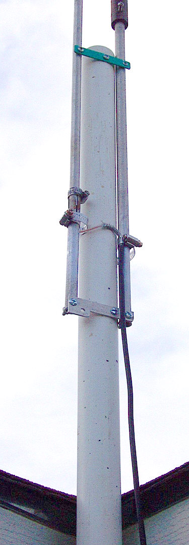
And, One non-conductive spacer from an old piece of plastic, PVC,
etc. This is used for support between short section and longest section
about 5 inches down from the air gap. (See pictures below....it is a shade
of green/blue in the picture)
This spacer and the bottom crossover of
the Slim Jim antenna is used to mount the antenna to a 10 foot piece of
PVC pipe at final installation by attaching self tapping screws thru each
one....see pictures.
Plus one section of non-conductive material
between shortest section and the top half. (dark color in picture) . This
came from another antenna "junk" pile. It is used only for support and an
insulator, also to keep the bottom and upper sections in line.
The Construction
I drilled holes suitable for the small bolts I
had near both ends of the longest section (57 1/2 inches), and one end of
the shortest section (19 1/4 inches) and one end of the section above the
shortest section. (37 1/4 inches)
Then I attached the "2 1/2 inch
"crossover" sections used as spacers and crossovers at bottom and top of
Slim Jim using the bolts, lock washers and nuts.
Then I attached the
air gap insulator/support between the lower and upper sections.
The construction of the Aluminum Slim Jim antenna was now finished
except for mounting to the 10 foot PVC pipe, checking and adjusting swr
and having some fun with it. Remember...this project was built from just
scraps of this and that found laying around my pile of "junk"....(junk is
defined by the XYL...it is gold to you and
I)!
Final Adjustment with a
surprise!
I
attached the Slim Jim antenna to the PVC pipe using the bottom crossover
section and the green/blue spacer on the shortest section with self
tapping screws. You may want to use a different arrangement such as nylon
ties along with the screws or put bolts all the way thru the PVC for extra
support. The antenna ends up mounted against the upper most part of the
PVC pipe with the pipe in the center of both vertical elements.
To attach the coax to the antenna feed points,
I used standard adjustable hose clamps that would tighten down on the
shield and center conductor of the rg58 coax that I used. I suggest you
use stainless steel clamps....again....I did not have any.
The center
conductor is attached to the LONGEST side of the antenna under the hose
clamp.
The shield is attached to the SHORTEST section under the hose
clamp. DO NOT tighten so as to cruch the coax. ( My feedpoint connections were just a temporary measure so
I could easily slide them up and down for swr tuning. ) They can be attached after tuning with screws, nuts, bolts,
etc.
I trimmed off enough of the black outer coax covering exposing
the shield about one inch and the center conductor extended so they could
be attached to the feedpoints.
I did not measure. Cut coax so the
shield and center conductor can be attached underneath the clamps. I
connected the coax center conductor first and brought the rest at a 90
degree angle over to the shortest side for it's attachment.
Tighten
the clamps at around 4 1/2 inches up from the bottom of the antenna. (This
measurement was derived at by my experimentation during tune up). Yours
may be different.
The clamps at the feed point connections may have to
be adjusted up or down for the best match, hence, the reason for the hose
clamps. (The first attempt I made was with the feed at about 3 inches from
the bottom.... and the antenna resonant point was way out of the 2 meter
band....about 138 mhz with an swr of around 3 to 1). This told me
that the Slim Jim was way too long......after adjusting the feed point
closer to the air gap at 4 1/2 inches from the bottom, I was in business!
These are the final swr readings with the
antenna up in it's final position....all of 10 feet above the ground
beside the house:
144MHz 1.2
145MHz 1.1
Mfj 259b read x = 0 52 ohms
146MHz
1.1
x = 0 52 ohms
147MHz
1.1
x = 0 54 ohms
148MHz 1.3
All with a 98 percent match according to the Mfj 259b
All lengths of the Slim Jim may be changed slightly either way
depending on your construction for better swr. You may not get that
perfect 1:1 reading.
THE
SURPRISE!
After I
stood back and marveled at my "new" Slim Jim, it dawned on me that
the bottom of the antenna was only about 8 inches from the metal roof
flashing under the shingles!
This was a NO NO according to all of the
Slim Jim articles I had researched on the Web.
The "freespace"
distance should be no less than about 20 inches (1/4 wave) from ANY metal
in ANY direction!
THE
HORROR!
I rechecked
the swr, resonant points, etc over the entire 2 meter band using the MFJ
259B, in case I had made an error, (not a mistake), but the numbers were
the same as before.
Now my curiosity came out showing it's ugly face,
so I managed to get the 10 foot piece of PVC pipe up higher so the bottom
of the antenna was at least 36 inches from ANY metal.....
Re-checked
the readings using the Mfj 259b and to my wonder.......
NO
CHANGE AT ALL!
I suspect that the freespace distance of 20
inches or more quoted in previous articles and research on this antenna is
used so the pattern will not distort up or down from the "8 degree" angle
of radiation from the ground. I have not done further research or testing
on the air to confirm this but hope to in the future. If any of you out
there wish to "model" this antenna using different distances from
surrounding metal....I am open to your input.
An air wound choke may be used at the base of the antenna to
help prevent rf on the feedline, creating difficulty with SWR readings,
and help prevent distorting the low angle pattern.. For 2 meters, the air
choke coil is about 4 turns of coax at 5 inches in diameter. Some builders
use it....some don't...I have not added one at this time but plan to in
the future to see if there is any effect on the
pattern.
One note of further
information for you should you decide to build
the Slim Jim.
During the period of time between this version and the
dismantling of the old Slim Jim, I decided to put it back up as a Slim Jim
antenna....take some S meter readings of area repeaters for a reference
and then re-convert the same antenna back to the old standard J Pole
......take some readings of the same repeaters and compare
them.
I found that the Slim Jim
could bring up several repeaters that the J Pole could not! No changes
were made between the two comparisons except the antennas!
This tells
me that the Slim Jim antenna has something going for it.....try one and
get something going for you.........HAVE FUN! EXPERIMENT, EXPERIMENT,
EXPERIMENT...
73 N4UJW
HAMUNIVERSE.COM
 
Notice the hollow insulator covering the air gap
at the
top of picture.


Hamuniverse.com uses Green Geeks Web
Hosting!
|
|
