In case of an imperfect match between the transmitter’s output impedance and the antenna’s impedance (both of them wich should be 50 ohm), some of the power transmitted will not be radiated and will return in the transmitter’s final amplifier stage to overload it, first by overheating and in serious cases even by damaging it.
To check the correct adaptation of the antenna, a device called SWR meter needs to be used; the achronim comes from Standing Wave Ratio, and it will determine the ratio between the transmitted power and the radiated power. In ideal cases this ratio should be 1:1, but in usual cases values of up to 1.5:1 are OK.
A SWR meter is very simple to build, you just need a type of transformer that will pick up the waves circulating in both ways, rectify the picked up voltage and measure it with a voltmeter. The schematic is below:

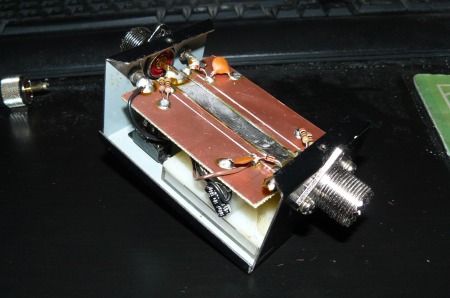
The transformer is made of 3 copper lines on a PCB, each of them 65mm long. The center line, that carries the power to the antenna, is 8mm wide, and the “secondaries” that pick up the signal for measurement are 4mm wide. The 68 ohm resistors are used to adapt the secondary lines to the 50 ohm impedance of the line and for large power measurements should be able to hold at least 0.5W of thermal dissipation. D1 and D2 are high-frequency rectifing diodes, for large power 1N4148 is OK but for precision and lower powers germanium-junction diodes like EFD 109 are a must.
Here is how this looks, mounted in the case of my old President TOS-01 SWR meter, that had burned-out PCB:
I combined more resistors to get a value as close to 68ohm as possible, this is important in getting the correct reflected power; replacing these with 100 ohm will make the SWR meter compatible with 75 ohm feed lines.
“DIR” will be a voltage proportional to the output power’s voltage, and “REF” will be a voltage proportional to the returning power’s voltage ( the voltage is proportional with the square of the power = you double the voltage, the power grows 4 times). Generally you want “REF” to be as close to zero as possible in the frequency band you are usually working, or at least in the middle of it. Mine is almost zero from 27.1Mhz up to 27.7Mhz, but this depends alot on the type of the antenna you are using.


[…] How to physique a SWR meter […]
[…] i will be using the same directional coupler i have used in the SWR meter (the one made on PCB) wich is directly influenced by the signal frequency, and because i want full […]
I have a workman meter it is new but does not work it reads to high How do I get this reading down. The meter is pretty simple inside. resisters 102 diodes i think a pot to calibrate on the out side a switch for fwd and ref and a nice meter swr ref power and field strength. Have any ideas.