
The Experiment: In this experiment were going make a Ham Radio 20 / 40 meter short coil loaded dipole antenna. The goal will be to keep the total length under 40 feet so that the dipole can be mounted on two 20 foot fiberglass pole to make a 20/40 meter rotatable dipole.

Table of Contents
1. Part List
2. Prototype
3. Notes
4. Conclusion
5. Reference Links
Part List:
1. One – Dipole Center Feed Connector
2. One – 50′ #14 AWG wire
3. Six – 16-14 AWG Ring Terminals
4. Two – 16-14 AWG Spade Terminals
5. Two – 31uh Loading coils
6. One – Spool #18 Magnetic wire
7. One Dipole Center Feed Connector
8. One – 8 foot 1-1/4 underground S40 rigid PVC conduit
^Top
Prototype:
1. Winding the 31uh loading coils:
1-1. Cut Two 3.450 inch coil forms of the 8 foot 1-1/4 underground S40 rigid PVC conduit.
1-2.

2. Preparing the elements
2-1. Cut two 15 foot lengths of #14 wire
2-1-1. Strip back 2″ of insulation on one end and 1/8″ of insulation of the other end.
2-1-2. Solder a ring terminal connector the the 1/8″ stripped end.
2-1-3. Slip a ring terminal over the 2″ end with the loop out, bend the 2″ end back on the ring terminal, then slip a spade terminal on the 2″ striped end and solder both terminal to the #14 wire.
2-1-4. Cut two 4 foot lengths of #14 wire
2-1-5. Strip back 1/8 of insulation.
2-1-6. Slip ring terminal over the striped end and solder ring terminal to #14 wire
2-1-7. Cut two 2 foot lengths of #14 wire
2-1-8. Strip back 1/8 of insulation.
2-1-9. Slip ring terminal over the striped end and solder ring terminal to #14 wire
3. Assembling the 20/40 meter dipole
3-1-1. Install 15 foot element to the Dipole Center Tee Connector 2″ stripped end to the connector.
3-1-2. Install the loading coil to the ring terminal on the 15 foot element, also connect the ring terminal from the 2 foot element to that terminal.
3-1-3. Install the ring terminal from the 4 foot element to the other end of the loading coil.
4. Setting the elements
4-1.1. Measured from the ring terminal, Set the 20 meter 2′ #14 sub to 1(one) foot 7(seven) inches.
4.1-2. Measured from the ring terminal, Set the 4′ #14 40 meter section to 3(three) foot 9(nine) inches.

5. Install the 20/40 meter dipole 20 feet off the ground and check the SWR for each band. Adjust the 20m stub and 40m section for low SWR at Center frequency.
Note: After tuning the 20 meter section and the 40 meter section. The total length of the prototype 20/40 meter coil loaded dipole was 38′ 2″. Off coarse this will very at different locations / heights.
Notes:
The link to the Dipole Center Feed Connector Build.
This is is how the 15′ element is connected to the Dipole Center Feed Tee Connector.

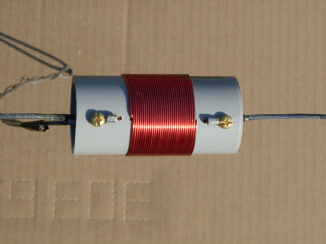
Photo Showing the Loading Coil / 20m fine tuning stub.

Conclusion:
Was surprised to see how well the 20/40 meter coil loaded dipole worked up at 20 feet , on 20m 1.0 to 1.5 SWR from 14.000 to 14.350 and 40 kilohertz spread at 1.6 SWR on 40m. Performance compared to the 40/80/20 coil loaded fan dipole center up at 32 feet was much better on 20 meter and good on 40 meter.
Final measurements each side:
Coax Ground Side – 20m section 16′ + 8″ adjustment tail 40m section 4′ 1″
Coax Center Conductor – 20m section 16′ + 8″ adjustment tail 40m section 3′ 6″
Reference Links:
1. Antenna Loading Coil Calculator
2. Coil Inductance Calculator
3. Helical Calculator
4. Coil Designer
^Top
