A 160 Meter Antenna
Hybrid Design
I finally managed to 'squeeze' in a resonant 160 meter antenna on my property... and it works!
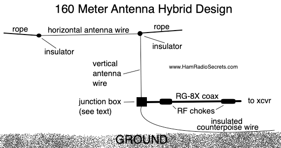
Normally, a dipole for 160 meters requires at least 260 feet of horizontal space, plus supporting ropes at each end. Furthermore, it is usually installed much too close to the ground, relative to its operating wavelength, which turns it into a NVIS (Near Vertical Incidence Skywave) antenna, only good for very short-range communications. (More on NVIS here.)
My shorter version has a vertical component to it, which increases the likelyhood of longer-range communications.
So. How did I manage to fit a resonant antenna on the 160 meter band in less space than normally required?
No, it's not a dipole with huge loading inductors. Nor is it a grounded quarter wave vertical with a huge loading inductor at its base and a whip, with lots of buried wire radials either.
Instead, it's a 'hybrid' design because, depending on how you look at it...
- It "looks" like an inverted 'L' antenna, yet it's not. A true inverted 'L' is a 5/16 vertical antenna worked against ground. Its vertical portion is bent to form an inverted 'L' (a vertical portion followed up there by a horizontal portion).
- It could also be viewed as a 160m off-center fed dipole antenna... with its long leg going up vertically, then away horizontally - and with its short leg lying flat on the ground and insulated from ground electrically!
- In fact, it looks more like an end-fed 1/4 wave 160 meter antenna (130 ft or 39.624 m long) which goes up some 25 feet (7-8 m), then over horizontally, at an average of 25 feet (7-8 m) above ground, to a tree at the far end of my property. It is worked against a counterpoise which is connected to the shielded side of the coaxial feed point.
For the counterpoise, I started with a 130-foot (39.624 m) length of insulated antenna wire.
On my first attempt, I had the entire length of counterpoise wire laid out on the ground, snug against the house foundations, and running all around the house to the opposite side.
But, working with a RigExpert antenna analyzer I soon found out that the antenna was resonant way below the 160 meter band. It was too long. Its resonant frequency was around 1.7 MHz!

Tuning the 160 Meter Antenna
Counterpoise
I decided to keep a 1/4 wave of wire up in the air as the 'active' part of the antenna. I then proceeded to shorten the counterpoise to bring the resonant frequency up above 1.8 MHz.
To do so easily, without wasting precious antenna wire by repeated pruning, I wound the end of the counterpoise back on itself in a rough coil about 6 inches in diameter.
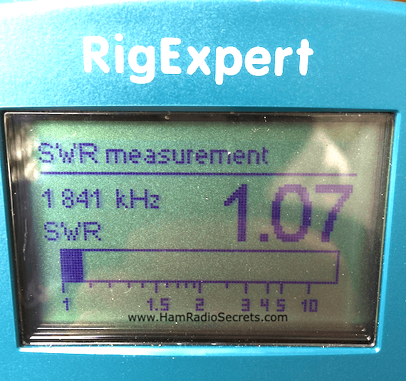
After a few attempts, I finally obtained resonance on 1.841 with an SWR of 1.07:1 which is within the lower part of the band where I intend to operate most of the time.
In the end, the counterpoise ended up measuring 62 feet overall, with the roughly coiled up portion at its end.
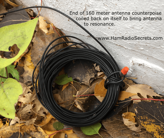
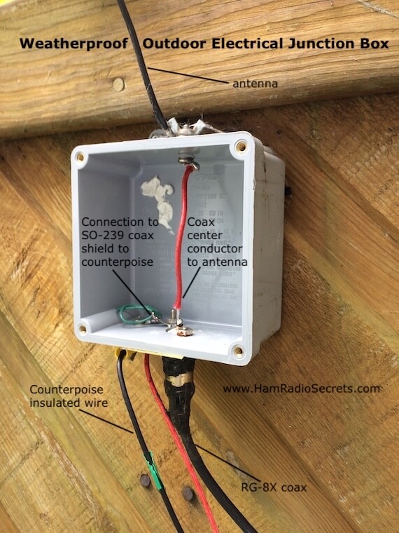
Notice (on the photo) that I have an orange electrical wire connector (waterproofed with CoaxSeal™) on the end of the counterpoise wire to prevent the 'live' inner conductor from making contact with the wet grass, wet leaves or wet snow.
Why? Because, if the inner conductor of the insulated counterpoise wire were to touch ground...
- the antenna would suddenly resonate on some other frequency, far removed from the 160 meter band;
- its behavior would become erratic;
- it could potentially damage your transceiver if it happened during transmission!
Feeding My 160 Meter Antenna
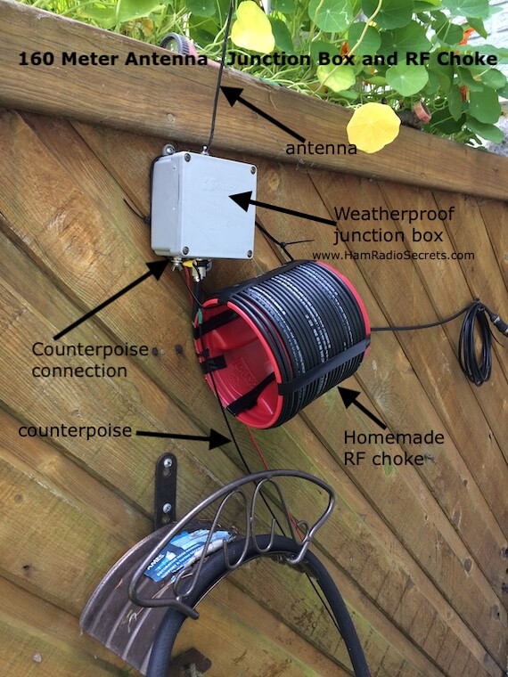
I feed my antenna with RG-8X coaxial cable. It is connected directly to the antenna, without a UNUN! The connections are protected by a weatherproof outdoor electrical junction box, installed outside, about four feet above ground.
The center conductor of the coax cable is connected to the aerial portion of the antenna while the coax shield is connected to the counterpoise portion.
(Disregard the red wire under the box. It's from an earlier experiment. I had forgotten to take it off before taking the photo.)
Ensuring Good Behavior
To prevent common mode RF from traveling back on the coax shield of the transmission line, I feed the antenna through a homemade RF choke made of 22 turns of RG-8X on a plastic form cut out of a Folgers coffee container.
The number of turns is probably overkill, even for a 160 meter antenna! It's not critical anyway because I also have a snap-on ferrite choke on the coax, just before it enters the house and another on the portion of the coax connecting to the transceiver. That many RF chokes is probably overkill too!
(Disregard the red wire under the box. It's from an earlier experiment. I had forgotten to take it off before taking the photo.)
I could always experiment taking the snap-on RF chokes off (not shown on the photo), one at a time, until I start to experience RF feedback in the shack... but, that's going to be for another day. ;) You see, the RF feedback could also be coming from my two other antennas:
- An off-center-fed 80 meter dipole that I use on all HF bands - from 80 to ten, sometimes even on the 6-meter band!
- A 40-meter dipole that I also sometimes use on the 15-meter band.
Without enough protection from common mode RF feedback, my 160 meter antenna's coaxial feedline would likely pick up some of the RF radiated when I transmit on any of these other two antennas, and feed it back to my equipment in the shack via the coax shield!
I like to avoid trouble which is why I like more RF chokes than not enough. Even a small amount of common mode RF feedback can cause your:
- SWR meter to display false readings;
- automatic antenna tuner to behave erratically and run the risk of being damaged or even damaging your transceiver's final amplification stage!
Even a little unwanted RF, running around the house, can cause weird things to happen. I became very conscious of this once when my burglar alarm went off while my wife was watching her favorite TV show. A near-fatal experience!
SWR Bandwidth
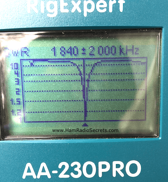
Here are some of the SWR readings after final installation (measured in late October):
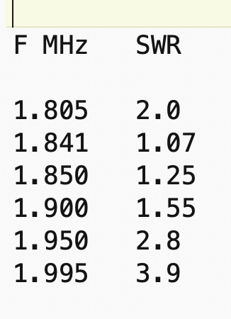 VSWR readings of the resonant 1/4 wave end-fed 160 meter antenna.
As you can see, my 160 meter antenna can cover at least half the 160 meter band within a 2:1 SWR. Any antenna tuner should be able to easily handle the higher SWR over the other half of the band.
Remember that you can choose to have the antenna resonate in the portion of the 160 meter band that you prefer - simply by adjusting the length of the counterpoise. Using an antenna analyzer simplifies this process considerably.
On the other hand, you could tune the counterpoise to make the antenna resonate in the middle of the band at 1.9 MHz. Any broad range 'L' network tuner will easily handle the higher SWR values at each end of the band.
A Word About Dimensions
Now, the above-mentioned dimensions of the aerial part, and its counterpoise, might be slightly different at your QTH because they will depend on:
- the height above ground of the horizontal portion of the aerial;
- the length of the vertical portion;
- the conductivity and dielectric properties of the ground below the antenna - both its aerial part and its counterpoise;
- not to mention surrounding structures within 1/2 wavelength (273 feet or 83.33 meters) of the antenna.
Anyway, you should be able to 'tune' the antenna to resonance easily enough by simply adjusting the length of the counterpoise, like I did, and thus, adapt it to its given environment.
Seasonal Considerations
Now, of course, the counterpoise was laid on the ground, in its final 'tuned' state, late in the month of October. I don't know yet what the resonant frequency of the antenna will be when it's buried under snow this winter.
Hopefully, the frequency of resonance will not shift prohibitively. ;)
One Last Remark
This 160 meter antenna is a "single band" antenna. The 160 meter band is not harmonically related to higher HF bands (except perhaps for the 60 meter band).
If you want to try to use this antenna on other HF bands anyway, you will need to use a wide range antenna tuner to handle the unpredictably high VSWR values.
73 de VE2DPE
Claude Jollet
7, Rue de la Rive, Notre-Dame-des-Prairies, Québec, Canada J6E 1M9
QTH Locator: FN36gb
Disclosure
If
you make a purchase via a link on this site, I may receive a small
commission on the transaction, at no extra cost to you. Thank you!


(One word queries work best)
HF Antennas
Section
Contents
VHF/UHF Antennas
FOUND THIS
SITE
USEFUL?
 Because you never know when...
VE2DPE
Is a member
in good standing
of
Also a proud member of an international community of solopreneurs
using SoloBuildIt!
(SBI!)
to promote my self-published eBooks
since 2005.
See my review
of this unique product for online businesses.
CQ CQ CQ
If you have a question, a comment or a topic you would like me to cover, please do not hesitate to ask here.
