
Over the winter I started work on constructing the three-element hex beam that I designed previously. This is “take two” on the basic hex beam idea, having first built a large 30m bamboo pull-up hex beam a few years ago. I’ve had time to figure out what I like and don’t like about that first version. The main good point is that it is an extremely effective antenna. With a wire set for each band, hex beams can be well-tuned for the bands they cover without compromise. The pattern is not too narrow and has good front-to-back directivity. The bamboo construction remains surprisingly robust. After almost three years in the air, I have not had to repair any of the spreaders and they look to have several more years of life in them. The pull-up feature is also a winner. It is an easy matter bring the antenna down if I want to change something or if something gets damaged.
The major shortcoming of the first version is the lack of any way to turn the beam other than manually using guide ropes hanging from the spreaders. Although this keeps me from sitting in the chair by the radio too much, it also can be a real nuisance, especially in bad weather or at night when I peer up at the antenna with a flashlight to ascertain where it is pointed so I can attempt to work that rare DX. The antenna does not turn freely without obstruction. The support rope and pull-up rope need to clear the spreaders and ultimately limit the height to which you can pull the antenna unless some effort is made to keep them out of the way. As a result, despite the overhanging branch pull point up more than 60 feet, the antenna only goes up about 35 feet before being obstructed by the ropes and various tree branches.
The Plan
It was time to pick a new spot, and to figure out how to use an old ChannelMaster TV antenna rotator to move my hex beam. The figures below show the concept.

This time rather than a single tree to support the pull-point I will use two (or three) trees. This makes it easier to hang the antenna further out from the tree trunk and offending branches and provides better clearance for the pull-point support ropes. The pull-up rope will exit through a hole in the hub of the antenna and be fastened to a stake in the ground directly under the antenna, again eliminating interference with the pull-up rope.

In the figure with more detail you can see the plan to achieve rotation. The upper pull-point includes the modified Channel Master antenna rotator, suspended from the pull-point support ropes. The 2x mechanical advantage pull-up rope is arranged to have the two supporting ropes spaced apart by about a foot so that the hanging antenna will want to follow the orientation of the upper pully block, which is turned by the rotator motor.
The Rotator
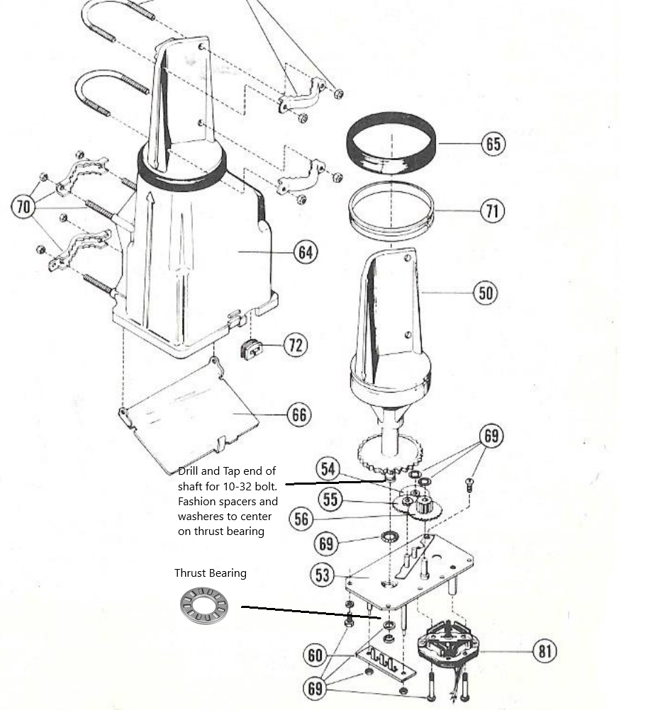
Most antenna rotators are designed to support an antenna mast from below. Hence gravity is pushing the two halves of the rotating components together. The Channel Master rotator is no different, but somehow I needed to make the rotator mechanics happy being pulled apart rather than pushed together. After some disassembly I was able to figure out how the mechanism worked. Below is an exploded diagram of the mechanism. Item 69 is the vertical thrust bearing for normal use. It sits between the end of the shaft and rides in an indentation in the baseplate 53. The only thing holding it together in tension is a small C-clip on the end of the shaft, which would never do as a bearing. I found a suitable thrust bearing, NTA1423 Needle Roller Thrust Bearing 7/8×1-7/16×5/64″, which would just fit on the backside of the plate. I tapped the end of the shaft for a 10-32 bolt and fashioned some washers and spacers to hold it all together. The weak link now is the tensile strength of the #10 bolt, which is ~1500lb. so should be okay. As an added precaution when I installed the unit, I included at safety rope linking the two halves of the unit so if something fails it will not come crashing down from 60 ft. above me.
There is nothing very fancy about this unit. To HOME the unit, the control just crashes the mechanism into a stop that stalls the motor. Since the antenna turns “backwards” when holding the top of the unit fixed, I had to reverse one of the wires to get the numbers to increase with increasing bearing angle. With my controller for this gizmo there seemed to be no way to electrically change the zero offset. Hence, I am living with a constant offset that I need to add/subtract to convert the controller readout to the actual pointing direction.

The picture above shows the rotator (version 2) about ready to be pulled up. I drilled out the lower two U-bolt holes in 50 to tie the pull-point support ropes. I used the threaded mounting holes in the base casting to bolt on a board which mounts the pulleys and the fixed tie point for the pull rope. When installing all of this, the control wire follows a piece of parachute cord as strain relief over to the rotator. (You could also follow one of the pull-point support ropes.) Everything was done from the ground with the aid of a tennis ball cannon to help place the support ropes in the trees. Once the rotator and its pull rope is suspended from the trees, the hardest part of the installation is complete.
The Antenna Construction Plan

The diagram above lays out the basic construction plan. I built a hub out of scraps of 2×6 cedar decking I had on hand. The hub gives the spreaders an initial elevation angle of about 30 degrees. Whether this was really necessary is a debatable question, but I was after more vertical spacing between the 10m and 12m wires. The mast is made of an 8′ cedar 2×4 with a cross piece on top for the rope pulleys. Wood is easy for making connection to the antenna wires using screws into the mast. I’m a little trepidatious about wood, sharp screws, wet weather and RF. However I’m only running 100W and if any problems develop I can build more RF-robust connections.
I cut the spreaders from my bamboo patch, looking for nice long ones not too thick at the base. For wire holders I again used slices of poly irrigation tubing lashed to the poles with string. (80 lb. fishing line works well for lashing material.)
I gave the poles and lashings a coat of spar varnish to protect everything from the weather and to lock in the lashings. That is me looking not all that happy to be painting varnish in the cold, but the poles liked it.
I cut the wires according to the recipe provided by the NEC model. On each end of the wires I placed an O-lug to provide and attachment for the spacer cords. The spacer cords just have a knot on each end that set the length of the space. The cords are cut a little long so you can use the position of the knot to adjust the spacer length accurately. On each side of the central mast I screwed in eye-hooks for the pull-in cords for the reflector and director wires. Assembling the wires for each band was a tedious but straightforward task. I was surprised how much of my 500′ spool of #14 THHN wire disappeared in this process.
Naturally, when I built it all and tested with the antenna analyzer, I was not happy and had to make various adjustments. That subject and the performance evaluation will warrant another article.

Optional Rotating Dipole for 30 and 40 meters
I discovered to my chagrin that the CQ DX Marathon, a year-long contest I enjoy participating in, has a height limit for wire antennas in the 100W “limited” category that excluded using my big wire for contacts for this contest. Hence, I needed a conforming replacement for at least a couple of the lower bands. My simple plan was to drape a 30m dipole over the top of the hex beam, allowing the ends to hang down. Then add traps and extensions to also get 40m. The model’s tuning and gain curves for this, now 7-band antenna, are shown below. The 30m band looks good, the 40m band is too sharp, but to be expected for a shortened dipole.


Lest we forget what we are trying to build, here’s the NEC model with draped dipole showing the 30m pattern.

Deployment Issues and Resolution
30m SWR Drift
The 30/40m trapped dipole was deployed and trimmed up to give a good tune on both 30m and 40m. However, when transmitting on the 30m band at more than ~25W I would see the SWR increase to unacceptable levels. My first suspicion was the trap capacitors. The problem was resolved by going to a trap made of RG58 Coax.
Rotation Issues
Getting all of the tree branches out of the way so that the antenna could be lifted to the full height took persistent effort. Several branches about 50 ft. off the ground needed to be cut using the rope chain saw. Rotational stiffness requires that the antenna lift-point be in close proximity to the rotator. If the antenna is not fully raised it is easy for the ropes to twist, at which point there is almost no restoring torque and the antenna can spin and twist the ropes to the whim of the wind. I doubled the length of the rotator arm from 12″ to about 24″ and this made the system much stiffer. Once the 30/40 dipole was added, tail ropes were installed on the ends of the dipole wires so that they could be used to anchor and steer the the antenna from the ground if necessary. Usually the tail ropes are clipped to the central pull-rope so that they do not impede rotation.
Major Expenses
| Item | Cost |
| 500 ft. #14 THHN wire | $50.00 |
| 500 ft. 3/8″ Polyester Rope | $150.00 |
| Channel Master Rotator (out of production?) | $120.00 |
| Coax Feed line (~150′ RG-11) | $50.00 |
The biggest expense I had was getting some good rope for the job. Finding a suitable light-weight antenna rotator may be more difficult if you do not have one on hand since it appears that the Channel Master version is no longer in production. All-in-all the costs are minimal for a directional seven-band antenna at fifty feet.

Antennas up in the trees do not photograph very well, but you can see antenna deployed in the photo above. The antenna is balanced and naturally hangs the way you want it to. If you look carefully, you can see the two lines between the rotator (version 1) and the top of the antenna mast. The pull rope goes from the right-side pulley on the rotator, down through an opening in the spreader hub, and down to the ground. A pair of “candy-cane” rebar stakes driven into the ground directly below the rotator provided a secure hold-down for the pull-rope. It takes just a couple of minutes to raise or lower the antenna. This is good because it can go up and down dozens of times when figuring out how to tune it up.
The antenna is now in service. There is still more tune-up to do, but the advantages over the old standard hex beam are clear. I used to love my old hex, but now I find that it sits neglected when the new three-element hex hears the marginal stations and the old one just can’t bring them in. Being able to listen to a station become loud and clear as I turn the new beam while operating the radio was worth the effort in itself. Standard hex beams are great antennas; the three element version kicks it up just another notch.

Thank you, Gary! Very cool and inspiring! I appreciate you great presentations on Ham radio subjects, especially antenna’s. I live on the side of a mountain with plenty of trees and room but getting signal out in certain directions is always a challenge.
Great picture of you too!
Ciao, 73.
Stephen Miller
KI7HJA