 Hits
Hits

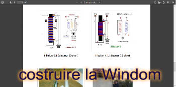
Costruire la Windom
Adattare l'impedenza della discesa a 50 ohm con il valore tipico di questa antenna, che sia aggira intorno ai 300 ohm
post 04 Dec 2024
Antenna Multibands Links →
Frecuencias de 7.1 Mhz y 3.650 Mhz
This dipole antenna is very good for those with small spaces.The antenna is designed with two load coils that cut the frequency in a given band
L'antenne Hertz-Conrad-Windom
The Hertz antenna, known in the USA under the name of Windom, is a multiband wire antenna made up of a horizontal radiating element of lambda / 2 length and fed at one third of its length by a single feeder wire.
La W3dzz
After a gentle cleaning of the group, I notice that the condenser is located in the center of the inductor
Log periodic 4 elements
My main limitation being this small mast, I had to make a tough compromise and my 12 elements turned more realistically into a 4 elements design. The 4 elements were calculated to be part of a 8 element design, in case I could build it in future times
Low-Cost Broadband Travelling Wave Dipole
A dipole can be modified by inserting resistive loading networks so as to produce standing waves between the feedpoint and the networks. The authors have, by adjustment of the networks and the dipole sections, developed a travelling wave dipole whose VSWR is less than 2:1 from 3 to 15 MHz and does not exceed 2.6 to 1 from 2.3 to at least 30 MHz
154
This dipole antenna is very good for those with small spaces.The antenna is designed with two load coils that cut the frequency in a given band
The Hertz antenna, known in the USA under the name of Windom, is a multiband wire antenna made up of a horizontal radiating element of lambda / 2 length and fed at one third of its length by a single feeder wire.
After a gentle cleaning of the group, I notice that the condenser is located in the center of the inductor
My main limitation being this small mast, I had to make a tough compromise and my 12 elements turned more realistically into a 4 elements design. The 4 elements were calculated to be part of a 8 element design, in case I could build it in future times
A dipole can be modified by inserting resistive loading networks so as to produce standing waves between the feedpoint and the networks. The authors have, by adjustment of the networks and the dipole sections, developed a travelling wave dipole whose VSWR is less than 2:1 from 3 to 15 MHz and does not exceed 2.6 to 1 from 2.3 to at least 30 MHz
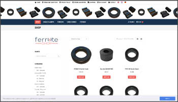
Ferrite Shop Ferrite-shop on-line shop, cable clamps,toroids, cable cores, technic,ferrite material choice
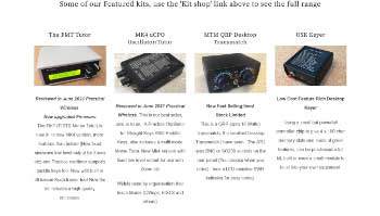
Amateur radio kits by Kanga US

Pcs Electronics RF power amplifiers-pallets archives-ABC of FM AM DAB+ DRM radio transmitters