 nt>
Hits
nt>
Hits

Power Amplifier for 136kHz 1kW
The design is somehow up-side-down. It is because the power FETs are mounted on the heat-sink which is on the top of the box
post 27 Jan 2024

Antenna 136KHz Links →
137 Khz CW transmitter
This is the TX freq logic, using a 27Mhz CB xtal and dividers to generate the 136 Khz The 27.407 Mhz is divides by 2 and then later by 10 in two 7493 counters then the 1.37035Mhz is feed into a 4017 decade counter, this one divide the freq by 10 again,Now the output freq is 137.035 Khz, the smart thing about the 4017 is that I can use the 10 outputs to generate the two outputs to my push-pull stage epending on how meny outputs used the pulse width can also be controlled
137 kHz experimental station
HiPerFET Power MOSFET IXFN55N50 500 volts at 55 amps, Currently running 28Volts at 14 amps input, Output 265 Watts
200W 136 kHz transmitter
My first transmission experiments on 136 kHz band where based on a little TX build around surplus component
600 Meter (VLF) Experiments as WD2XSH/22 ANTENNAS
The grey metal box at the bottom of the loop houses the tuning capacitor bank and the ferrite core matching transformer
70
This is the TX freq logic, using a 27Mhz CB xtal and dividers to generate the 136 Khz The 27.407 Mhz is divides by 2 and then later by 10 in two 7493 counters then the 1.37035Mhz is feed into a 4017 decade counter, this one divide the freq by 10 again,Now the output freq is 137.035 Khz, the smart thing about the 4017 is that I can use the 10 outputs to generate the two outputs to my push-pull stage epending on how meny outputs used the pulse width can also be controlled
HiPerFET Power MOSFET IXFN55N50 500 volts at 55 amps, Currently running 28Volts at 14 amps input, Output 265 Watts
My first transmission experiments on 136 kHz band where based on a little TX build around surplus component
The grey metal box at the bottom of the loop houses the tuning capacitor bank and the ferrite core matching transformer
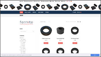
Ferrite Shop Ferrite-shop on-line shop, cable clamps,toroids, cable cores, technic,ferrite material choice
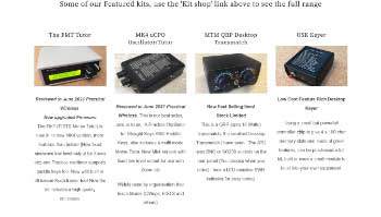
Amateur radio kits by Kanga US
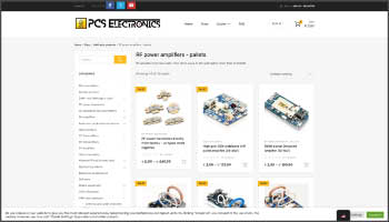
Pcs Electronics RF power amplifiers-pallets archives-ABC of FM AM DAB+ DRM radio transmitters